WARNING AND INDICATOR SYSTEM
Using the SSTs (NGS tester set) or a dwell tacho
tester
Caution
• If the engine speed exceeds the allowable
range, the engine could be damaged.
Therefore, when inspecting the tachometer,
do not allow the engine speed to exceed
the allowable range indication on the
tachometer.
1. Follow the appropriate procedure for using the
SSTs (NGS tester set) or a dwell tacho tester.
Using the SSTs (NGS tester set)
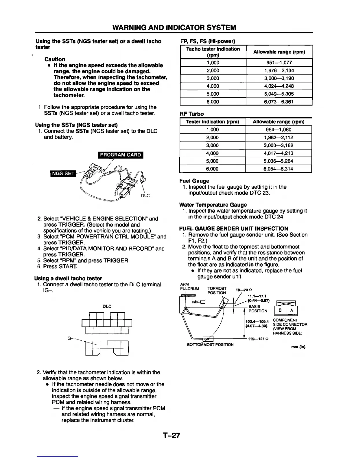
1. Connect the SSTs (NGS tester set) to the DLC
and battery.
PROGRAM CARD
FP, FS, FS (Hi-power)
2. Select “VEHICLE & ENGINE SELECTION” and
press TRIGGER. (Select the model and
specifications of the vehicle you are testing.)
3. Select “PCM-POWERTRAIN CTRL MODULE” and
press TRIGGER.
4. Select “PID/DATA MONITOR AND RECORD” and
press TRIGGER.
5. Select “RPM” and press TRIGGER.
6. Press START.
Using a dwell tacho tester
1. Connect a dwell tacho tester to the DLC terminal
IG-.
DLC
/
Tacho tester indication
(rpm)
Allowable range (rpm)
1,000
951—1,077
2,000
1,976—2,134
3,000 3,000—3,190
4,000
4,024— 4,248
5,000 5,049—5,305
6,000 6,073—6,361
RF Turbo
Tester indication (rpm)
Allowable range (rpm)
1,000
964—1,060
2,000
1,982—2,112
3,000
3,000—3,162
4,000 4,017—4,213
5,000
5,036—5,264
6,000
6,054—6,314
Fuel Gauge
1. Inspect the fuel gauge by setting it in the
input/output check mode DTC 23.
Water Temperature Gauge
1. Inspect the water temperature gauge by setting it
in the input/output check mode DTC 24.
FUEL GAUGE SENDER UNIT INSPECTION
1. Remove the fuel gauge sender unit. (See Section
F1.F2.)
2. Move the float to the topmost and bottommost
positions, and verify that the resistance between
terminals A and B of the unit and the position of
the float are as indicated in the figure.
• If they are not as indicated, replace the fuel
gauge sender unit.
18—20 0
11.1—17.1
{0.44—0.67}
BASIS
POSITION
B
103.4— 109.4 COMPONENT
{4.07—4.30}
119—121 Q
BOTTOMMOST POSITION
SIDE CONNECTOR
(VIEW FROM
HARNESS SIDE)
mm {in}
2. Verify that the tachometer indication is within the
allowable range as shown below.
• If the tachometer needle does not move or the
indication is outside of the allowable range,
inspect the engine speed signal transmitter
PCM and related wiring harness.
— If the engine speed signal transmitter PCM
and related wiring harness are normal,
replace the instrument cluster.
T-27


 To Next Page