EXTERIOR LIGHTING SYSTEM
FLASHER UNIT INSPECTION
1. Remove the bracket and pull it toward you.
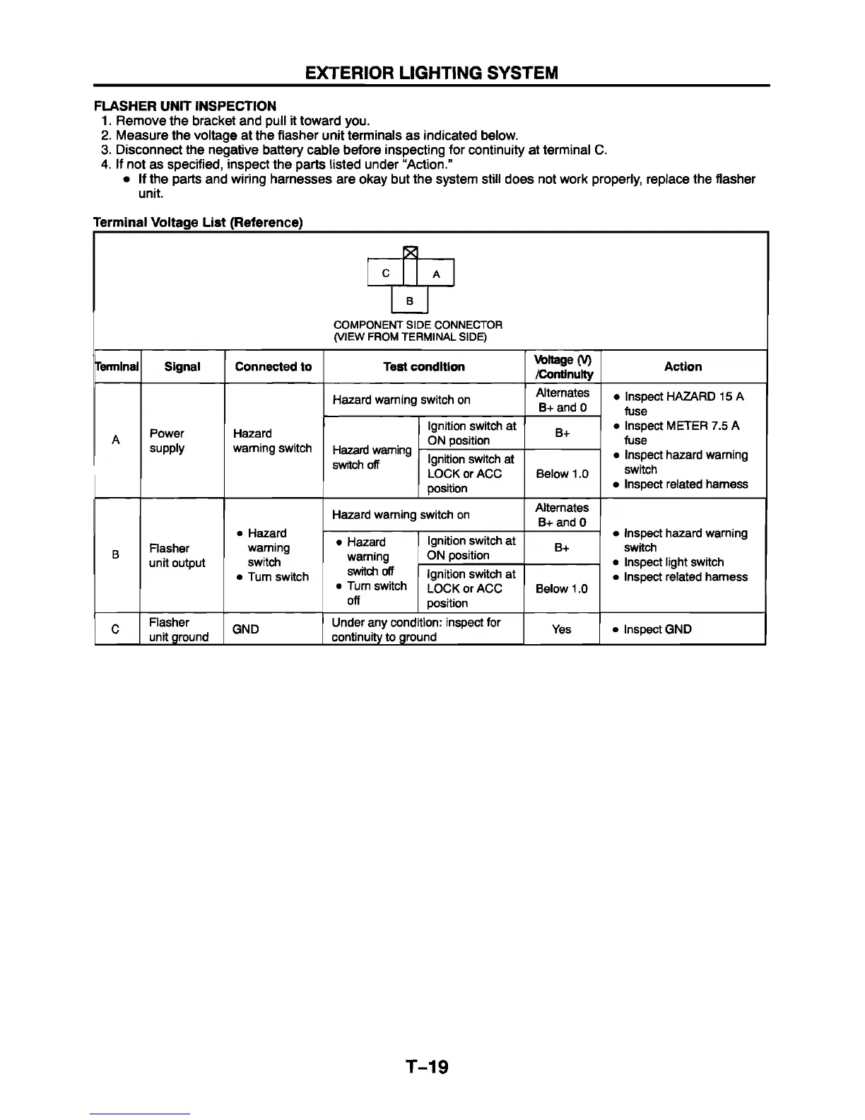
2. Measure the voltage at the flasher unit terminals as indicated below.
3. Disconnect the negative battery cable before inspecting for continuity at terminal C.
4. If not as specified, inspect the parts listed under “Action.”
• If the parts and wiring harnesses are okay but the system still does not work properly, replace the flasher
unit.
Terminal Voltage List (Reference)
_____________________________________________________________
c
A
B
COMPONENT SIDE CONNECTOR
(VIEW FROM TERM INAL SIDE)
Terminal
Signal Connected to
Test condition
Voltage (V)
/Continuity
Action
A
Power
supply
Hazard
warning switch
Hazard warning switch on
Alternates
B+ and 0
• Inspect HAZARD 15 A
fuse
• Inspect METER 7.5 A
fuse
• Inspect hazard warning
switch
• Inspect related harness
Hazard warning
switch off
Ignition switch at
ON position
B+
Ignition switch at
LOCK or ACC
position
Below 1.0
B
Flasher
unit output
• Hazard
warning
switch
• Turn switch
Hazard warning switch on
Alternates
B+ and 0
• Inspect hazard warning
switch
• Inspect light switch
• Inspect related harness
• Hazard
warning
switch off
• Turn switch
off
Ignition switch at
ON position
B+
Ignition switch at
LOCK or ACC
position
Below 1.0
C
Flasher
unit ground
GND
Under any condition: inspect for
continuity to ground
Yes • Inspect GND
T-19


 To Next Page