TROUBLESHOOTING
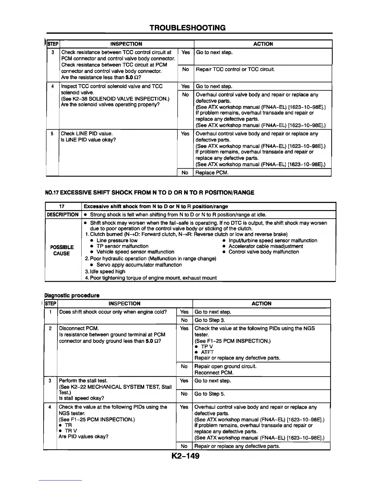
STEP INSPECTION ACTION
3
Check resistance between TCC control circuit at
PCM connector and control valve body connector.
Check resistance between TCC circuit at PCM
connector and control valve body connector.
Are the resistance less than 5.0 ft?
Yes Go to next step.
No Repair TCC control or TCC circuit.
4 Inspect TCC control solenoid valve and TCC
solenoid valve.
(See K2-38 SOLENOID VALVE INSPECTION.)
Are the solenoid valves operating properly?
Yes Go to next step.
No Overhaul control valve body and repair or replace any
defective parts.
(See ATX workshop manual (FN4A-EL) [1623-10-98E].)
If problem remains, overhaul transaxle and repair or
replace any defective parts.
(See ATX workshop manual (FN4A-EL) [1623-10-98E].)
5
Check LINE PID value.
Is LINE PID value okay?
Yes
Overhaul control valve body and repair or replace any
defective parts.
(See ATX workshop manual (FN4A-EL) [1623-10-98E])
If problem remains, overhaul transaxle and repair or
replace any defective parts.
(See ATX workshop manual (FN4A-EL) [1623-10-98E].)
No
Replace PCM.
N0.17 EXCESSIVE SHIFT SHOCK FROM N TO D OR N TO R POSITION/RANGE
17
Excessive shift shock from N to D or N to R position/range
DESCRIPTION • Strong shock Is felt when shifting from N to D or N to R position/range at idle.
POSSIBLE
CAUSE
• Shift shock may worsen when the fail-safe is operating. If no DTC is output, the shift shock may worsen
due to poor operation of the control valve body or sticking of the clutch.
1. Clutch burned (N-»D: Forward clutch, N-»R: Reverse clutch or low and reverse brake)
• Line pressure low • Input/turbine speed sensor malfunction
• TP sensor malfunction • Accelerator cable misadjustment
• Vehicle speed sensor malfunction • Control valve body malfunction
2. Poor hydraulic operation (Malfunction in range change)
• Servo apply accumulator malfunction
3. Idle speed high
4. Poor tightening torque of engine mount, exhaust mount
Diagnostic procedure
STEP INSPECTION ACTION
1 Does shift shock occur only when engine cold? Yes
Go to next step.
No Go to Step 3.
2 Disconnect PCM.
Is resistance between ground terminal at PCM
connector and body ground less than 5.0 Q?
Yes Check the value at the following PIDs using the NGS
tester.
(See F1-25 PCM INSPECTION.)
• TPV
• AT FT
Repair or replace any defective parts.
No
Repair open ground circuit.
Reconnect PCM.
3
Perform the stall test.
(See K2-22 MECHANICAL SYSTEM TEST, Stall
Test.)
Is stall speed okay?
Yes
Go to next step.
No
Go to Step 5.
4 Check the value at the following PIDs using the
NGS tester.
(See F1-25 PCM INSPECTION.)
• TR
• TR V
Are PID values okay?
Yes Overhaul control valve body and repair or replace any
defective parts.
(See ATX workshop manual (FN4A-EL) [1623-10-98E].)
If problem remains, overhaul transaxle and repair or
replace any defective parts.
(See ATX workshop manual (FN4A-EL) [1623-10-98E].)
No Repair or replace any defective parts.
K2-149



 To Next Page