ON-BOARD DIAGNOSTIC
DTC6
DTC6 Driver-side air bag module system
DETECTION
CONDITION
Warning
• Detection conditions are for understanding DTC outline before performing inspection.
Performing inspection with only detection conditions may cause injury due to operating
error or damage the system. When performing inspection, always follow inspection
procedure.
• Abnormal resistance (other than 1.85—3.46 £2) detected in driver-side air bag module circuit
• Short circuit in wiring harness related SAS unit terminal 2D or 2G
POSSIBLE
CAUSE
• Driver-side air bag module malfunction
• Clock spring malfunction
• Malfunction of connectors between clock spring and SAS unit
• Open or short circuit in wiring harness between clock spring and SAS unit
• SAS unit malfunction
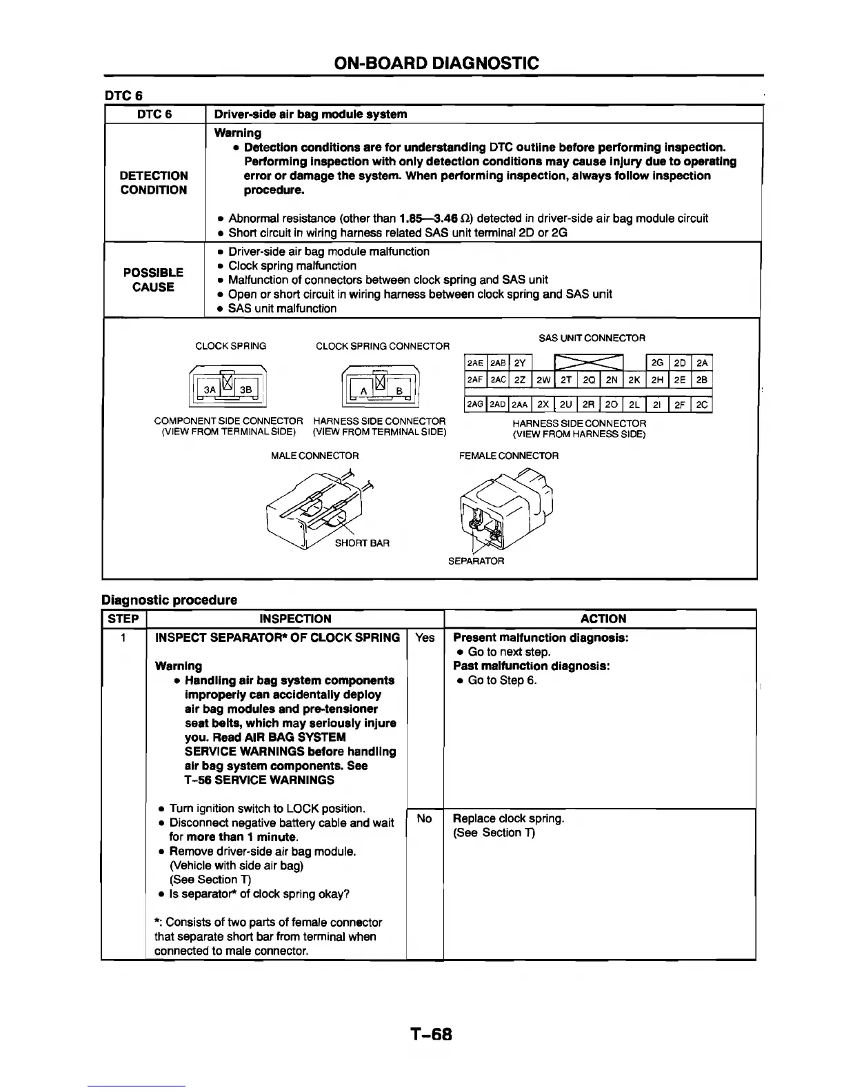
CLOCK SPRING
CLOCK SPRING CONNECTOR
3A 3B
COMPONENT SIDE CONNECTOR HARNESS SIDE CONNECTOR
(VIEW FROM TERM INAL SIDE) (VIEW FROM TERMINAL SIDE)
MALECONNECTOR
SAS UNIT CONNECTOR
2AE 2AB
2Y
X
2G
2D 2A
2AF
2AC
2Z
2W 2T 2Q 2N 2K
2H
2E
2B
2AG 2AD
2AA
2X 2U
2R 20
2L
21
2F 2C
HARNESS SIDE CONNECTOR
(VIEW FROM HARNESS SIDE)
FEMALECONNECTOR
Diagnostic procedure
STEP INSPECTION ACTION
1 INSPECT SEPARATOR* OF CLOCK SPRING
Warning
• Handling air bag system components
improperly can accidentally deploy
air bag modules and pre-tensioner
seat belts, which may seriously injure
you. Read AIR BAG SYSTEM
SERVICE WARNINGS before handling
air bag system components. See
T-56 SERVICE WARNINGS
• Turn ignition switch to LOCK position.
• Disconnect negative battery cable and wait
for more than 1 minute.
• Remove driver-side air bag module.
(Vehicle with side air bag)
(See Section T)
• Is separator* of clock spring okay?
*: Consists of two parts of female connector
that separate short bar from terminal when
connected to male connector.
Yes Present malfunction diagnosis:
• Go to next step.
Past malfunction diagnosis:
• Go to Step 6.
No
Replace clock spring.
(See Section T)
T-68


 To Next Page