ON-BOARD DIAGNOSTIC
STEP
INSPECTION ACTION
6 VERIFY AFTER REPAIR PROCEDURE
• Perform “After Repair Procedure."
(See F1 36 AFTER REPAIR PROCEDURE)
• Are any DTCs present?
Yes Go to applicable DTC inspection.
(See F1-37 DTC TABLE)
No
Troubleshooting completed.
DTC P0335
Except for GF4A-EL Models
DTC P0335
CKP sensor circuit malfunction
DETECTION
CONDITION
If PCM does not receive input voltage from CKP sensor for 4.2 seconds while MAF is
1.99 g/sec. {0.257 Ib./min.} or above, PCM determines that CKP circuit has a malfunction.
POSSIBLE
CAUSE
CKP sensor malfunction
Connector or terminal malfunction
CKP sensor is dirty.
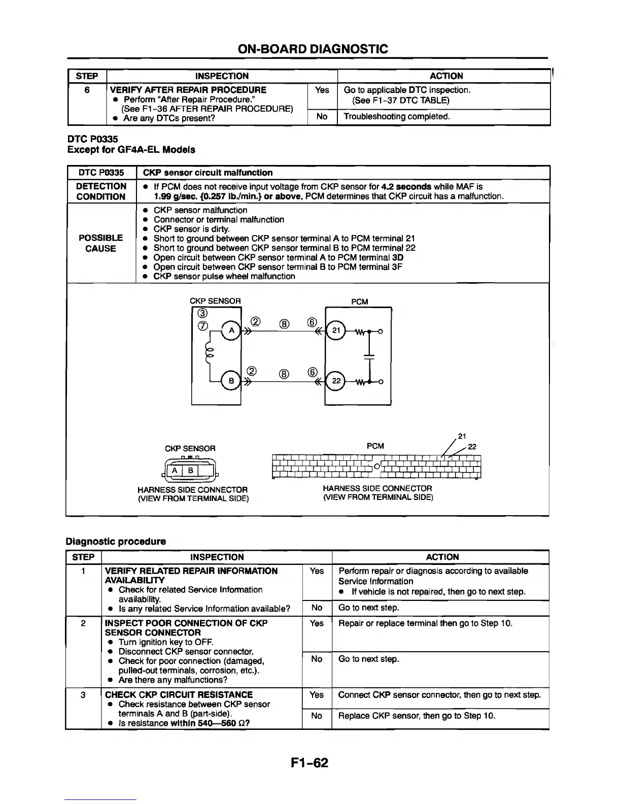
Short to ground between CKP sensor terminal A to PCM terminal 21
Short to ground between CKP sensor terminal B to PCM terminal 22
Open circuit between CKP sensor terminal A to PCM terminal 3D
Open circuit between CKP sensor terminal B to PCM terminal 3F
CKP sensor pulse wheel malfunction
CKP SENSOR
PCM
CKP SENSOR
n n n
HARNESS SIDE CONNECTOR
(VIEW FROM TERMINAL SIDE)
PCM
W ï i ï i 'i ï .ï iiJ
t x i i i i i i i i i i
.21
T r r
T T
x r
HARNESS SIDE CONNECTOR
(VIEW FROM TERMINAL SIDE)
-22
ti¿i'í|i|¡|l I i! X!
I I I I I I I ri II II J
Diagnostic procedure
STEP INSPECTION
ACTION
1 VERIFY RELATED REPAIR INFORMATION
AVAILABILITY
• Check for related Service Information
availability.
• Is any related Service Information available?
Yes Perform repair or diagnosis according to available
Service Information
• If vehicle is not repaired, then go to next step.
No Go to next step.
2 INSPECT POOR CONNECTION OF CKP
SENSOR CONNECTOR
• Turn ignition key to OFF.
• Disconnect CKP sensor connector.
• Check for poor connection (damaged,
pulled-out terminals, corrosion, etc.).
• Are there any malfunctions?
Yes Repair or replace terminal then go to Step 10.
No Go to next step.
3
CHECK CKP CIRCUIT RESISTANCE
• Check resistance between CKP sensor
terminals A and B (part-side).
• Is resistance within 540—560 £2?
Yes Connect CKP sensor connector, then go to next step.
No
Replace CKP sensor, then go to Step 10.
F1-62