CONTROL SYSTEM
Monitor item
(Definition)
Unit/
Condition
Condition/Specification Action
PCM
terminal
TP V
(Accelerator
position signal
voltage)
V
Accelerator pedal is depressed:
3.1—3.5 V
Accelerator pedal is released:
0.5—0.7 V
Inspect accelerator position sensor.
See F2-21 ACCELERATOR
POSITION SENSOR
INSPECTION
2F
TP2 V
(Accelerator
position signal
voltage for
monitoring)
V
Accelerator pedal is depressed:
3.1—3.5 V
Accelerator pedal is released:
0.5—0.7 V
Inspect accelerator position sensor.
See F2-21 ACCELERATOR
POSITION SENSOR
INSPECTION
2H
VS
(Vehicle speed)
KMH KPH
Vehicle speed is 20 km/h {12.5 mph}:
20 km/h {12.5 mph}
Vehicle speed is 40 km/h {25 mph}:
40 km/h {25 mph}
Inspect VSS.
See T-26 INSTRUMENT
CLUSTER INSPECITON
3L
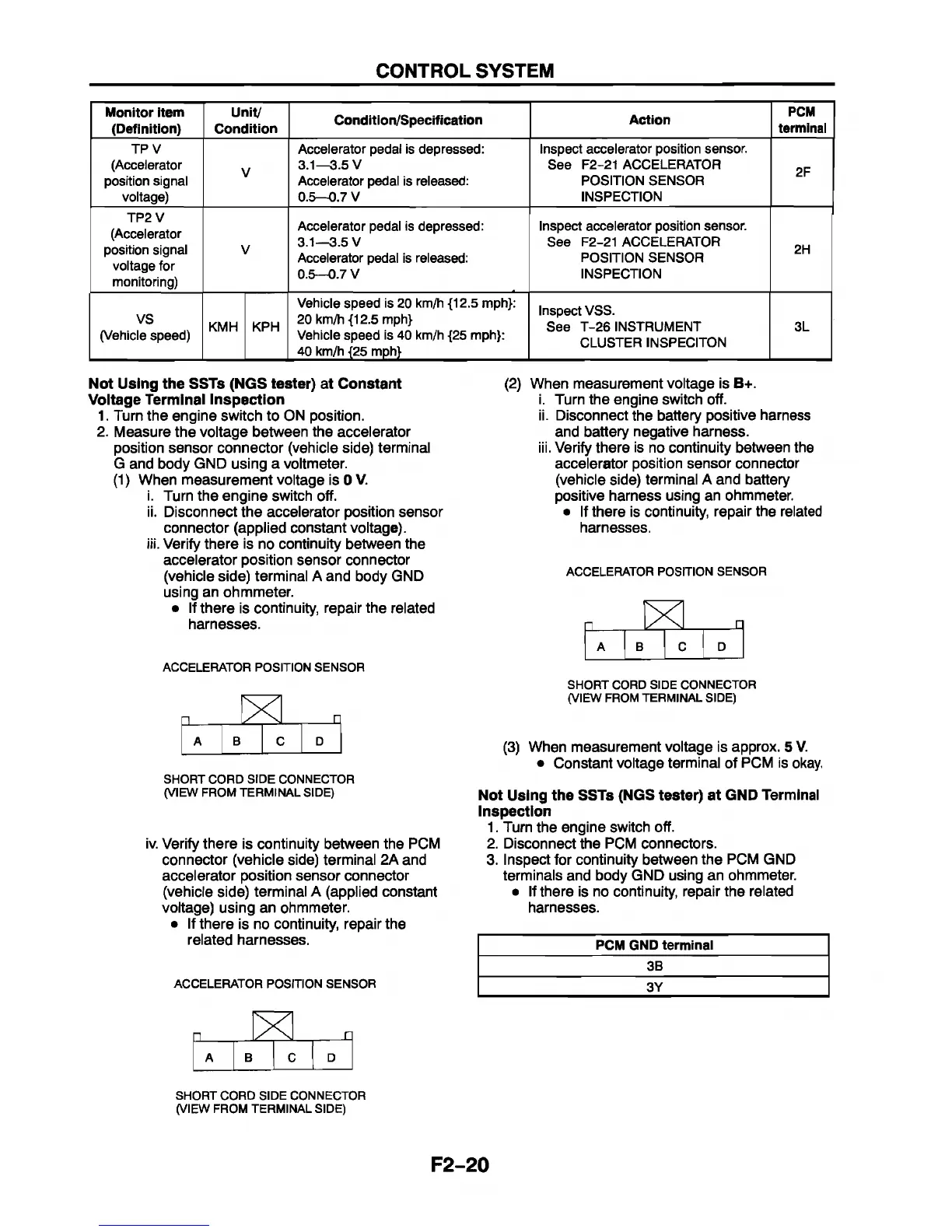
Not Using the SSTs (NGS tester) at Constant
Voltage Terminal Inspection
1. Turn the engine switch to ON position.
2. Measure the voltage between the accelerator
position sensor connector (vehicle side) terminal
G and body GND using a voltmeter.
(1) When measurement voltage is 0 V.
i. Turn the engine switch off.
ii. Disconnect the accelerator position sensor
connector (applied constant voltage).
Verify there is no continuity between the
accelerator position sensor connector
(vehicle side) terminal A and body GND
using an ohmmeter.
• If there is continuity, repair the related
harnesses.
(2)
in
When measurement voltage is B+.
i. Turn the engine switch off.
ii. Disconnect the battery positive harness
and battery negative harness.
iii. Verify there is no continuity between the
accelerator position sensor connector
(vehicle side) terminal A and battery
positive harness using an ohmmeter.
• If there is continuity, repair the related
harnesses.
ACCELERATOR POSITION SENSOR
X □
A I B
C I D
ACCELERATOR POSITION SENSOR
n
[X
n
A B
C
D
SHORT CORD SIDE CONNECTOR
(VIEW FROM TERMINAL SIDE)
iv. Verify there is continuity between the PCM
connector (vehicle side) terminal 2A and
accelerator position sensor connector
(vehicle side) terminal A (applied constant
voltage) using an ohmmeter.
• If there is no continuity, repair the
related harnesses.
ACCELERATOR POSITION SENSOR
SHORT CORD SIDE CONNECTOR
(VIEW FROM TERMINAL SIDE)
(3) When measurement voltage is approx. 5 V.
• Constant voltage terminal of PCM is okay.
Not Using the SSTs (NGS tester) at GND Terminal
Inspection
1. Turn the engine switch off.
2. Disconnect the PCM connectors.
3. Inspect for continuity between the PCM GND
terminals and body GND using an ohmmeter.
• If there is no continuity, repair the related
harnesses.
PCM GND terminal
3B
3 Y
n
n
A B
O
a
SHORT CORD SIDE CONNECTOR
(VIEW FROM TERMINAL SIDE)
F2-20


 To Next Page