DRIVE SHAFT
ABS Sensor Rotor Assembly Note
Caution
• Verify the direction of the sensor rotor.
1. Set a new ABS sensor rotor on the drive shaft and
press it on using the SST.
Boot Assembly Note
Note
• The wheel side and transaxle side boots are
different.
• Use the specified grease supplied in the boot
kit.
1. Fill the boot (wheel side) with the specified grease.
Grease amount
85—105 g {3.0—3.7 oz>
2. With the splines of the shaft still wrapped in tape
from disassembly, install the boot.
3. Remove the tape.
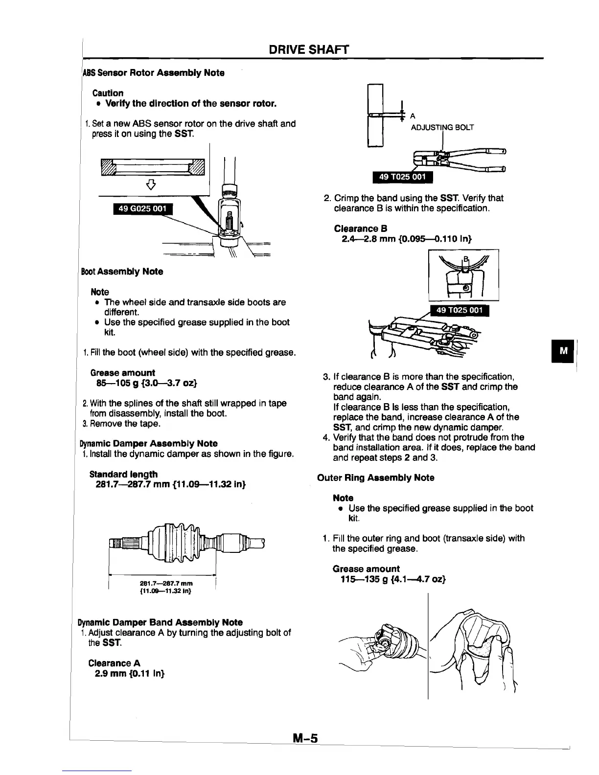
Dynamic Damper Assembly Note
1. Install the dynamic damper as shown in the figure.
Standard length
281.7—287.7 mm {11.09—11.32 in}
281.7—287.7 mm
{11.09—11.32 In}
Dynamic Damper Band Assembly Note
1. Adjust clearance A by turning the adjusting bolt of
the SST.
Clearance A
2.9 mm {0.11 In}
A
49 T025 001
2. Crimp the band using the SST. Verify that
clearance B is within the specification.
Clearance B
2.4—2.8 mm {0.095—0.110 In}
3. If clearance B is more than the specification,
reduce clearance A of the SST and crimp the
band again.
If clearance B is less than the specification,
replace the band, increase clearance A of the
SST, and crimp the new dynamic damper.
4. Verify that the band does not protrude from the
band installation area. If it does, replace the band
and repeat steps 2 and 3.
Outer Ring Assembly Note
Note
• Use the specified grease supplied in the boot
kit.
1. Fill the outer ring and boot (transaxle side) with
the specified grease.
Grease amount
115—135 g {4.1—4.7 oz}