ON-BOARD DIAGNOSTIC
}DTC P0117
Except for GF4A-EL Models
DTC P0117
ECT circuit low input
DETECTION
CONDITION
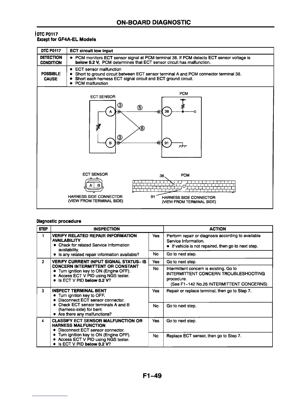
• PCM monitors ECT sensor signal at PCM terminal 38. If PCM detects ECT sensor voltage is
below 0.2 V, PCM determines that ECT sensor circuit has malfunction.
POSSIBLE
CAUSE
• ECT sensor malfunction
• Short to ground circuit between ECT sensor terminal A and PCM connector terminal 38.
• Short each harness ECT signal circuit and ECT ground circuit.
• PCM malfunction
PCM
ECT SENSOR
38,
PCM
( / —
A
-----
^
B
i
* \
-----
-----
I
X
-----
n
-----
'
^ ■ I Ï iÏ i'iÏ i'l^ i' i'i'i'iV i'i'i'iV i'i'i'j
(VIEW FROM TERMINAL SIDE)
91 HARNESS SIDE CONNECTOR
(VIEW FROM TERMINAL SIDE)
Diagnostic procedure
STEP
INSPECTION ACTION
1 VERIFY RELATED REPAIR INFORMATION
AVAILABILITY
• Check for related Service Information
availability.
• Is any related repair information available?
Yes
Perform repair or diagnosis according to available
Service Information.
• If vehicle is not repaired, then go to next step.
No Go to next step.
2 VERIFY CURRENT INPUT SIGNAL STATUS- IS
CONCERN INTERMITTENT OR CONSTANT
• Turn ignition key to ON (Engine OFF).
• Access ECT V PID using NGS tester.
• Is ECT V PID below 0.2 V?
Yes Go to next step.
No
Intermittent concern is existing. Go to
INTERMITTENT CONCERN TROUBLESHOOTING
procedure.
(See F1-142 No.26 INTERMITTENT CONCERNS)
3
INSPECT TERMINAL BENT
• Turn ignition key to OFF.
• Disconnect ECT sensor connector.
• Check ECT sensor terminals A and B
(harness-side) for bent.
• Are there any malfunctions?
Yes
Repair or replace terminal, then go to Step 7.
No Go to next step.
4 CLASSIFY ECT SENSOR MALFUNCTION OR
HARNESS MALFUNCTION
• Disconnect ECT sensor connector.
• Turn ignition key to ON (Engine OFF).
• Access ECT V PID using NGS tester.
• Is ECT V PID below 0.2 V?
Yes Go to next step.
No
Replace ECT sensor, then go to Step 7.
F1-49


 To Next Page