CONTROL SYSTEM
I CONTROL SYSTEM
OUTLINE
• A potentiometer with two built-in signal circuits, which are the current main signal circuit and a newly utilized
monitor signal circuit, has been created. The monitor signal regularly monitors the main signal and reliability
has been improved.
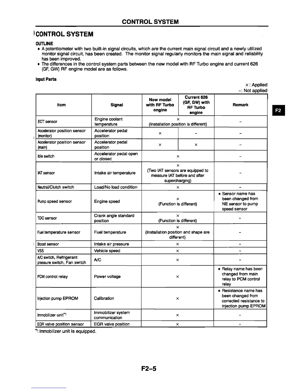
• The differences in the control system parts between the new model with RF Turbo engine and current 626
(GF, GW) RF engine model are as follows.
Input Parts
x : Applied
______________________________________________________________________________
Not applied
Item
Signal
New model
with RF Turbo
engine
Current 626
(GF, GW) with
RF Turbo
engine
Remark
ECT sensor
Engine coolant
temperature
X
(Installation position is different)
-
Accelerator position sensor
(monitor)
Accelerator pedal
position
X
- -
Accelerator position sensor
(main)
Accelerator pedal
position
X
X
-
Idle switch
Accelerator pedal open
or closed
X
-
IAT sensor
Intake air temperature
X
(Two IAT sensors are equipped to
measure IAT before and after
supercharging)
-
Neutral/Clutch switch Load/No load condition
X
-
Pump speed sensor
Engine speed
X
(Function is different)
• Sensor name has
been changed from
NE sensor to pump
speed sensor
TDC sensor
Crank angle standard
position
X
(Function is different)
-
Fuel temperature sensor Fuel temperature
X
(Installation position and shape are
different)
-
Boost sensor Intake air pressure
X
-
VSS
Vehicle speed
X -
A/C switch, Refrigerant
pressure switch, Fan switch
A/C
X
-
PCM control relay
Power voltage
X
• Relay name has been
changed from main
relay to PCM control
relay
Injection pump EPROM
Calibration
X
• Resistance name has
been changed from
corrected resistance to
injection pump EPROM
Immobilizer unit*1
Immobilizer system
communication
X
-
EGR valve position sensor EGR valve position
X
-
\ Immobilizer unit is equipped.
F2-5


 To Next Page