ON-BOARD DIAGNOSTIC
k DTC P0123
Except for GF4A-EL Models
DTC P0123 TP circuit high input
DETECTION
CONDITION
If PCM detects TP sensor voltage at PCM terminal 89 is above 4.8 V after engine start, PCM
determines that TP circuit has a malfunction.
POSSIBLE
CAUSE
TP sensor malfunction
Connector or terminal malfunction
Open circuit between TP sensor terminal C and PCM terminal 91
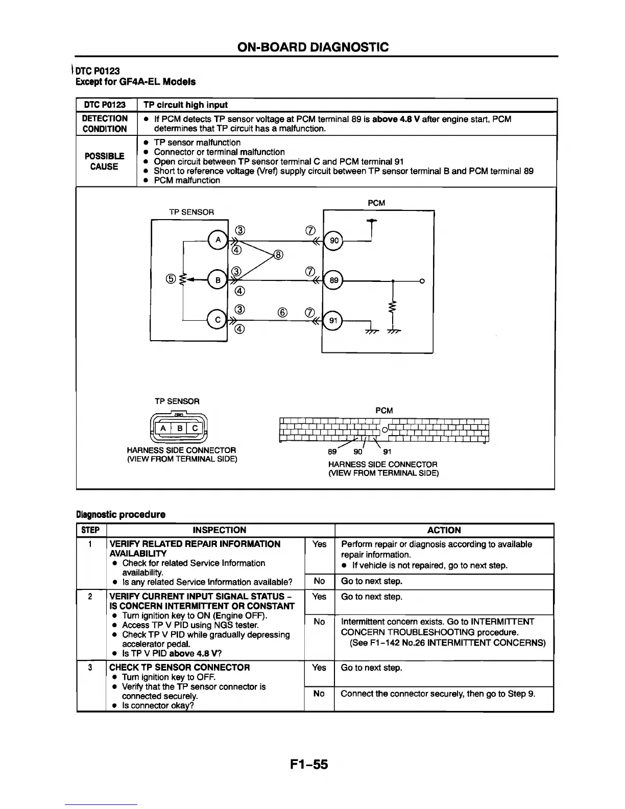
Short to reference voltage (Vref) supply circuit between TP sensor terminal B and PCM terminal 89
PCM malfunction
PCM
TP SENSOR
HARNESS SIDE CONNECTOR
(VIEW FROM TERMINAL SIDE)
PCM
I, I . I. I , I , I . I . I, I , I, I I I I I I I I
i ; e n , i ; i , i , l; i x c i , i :Q ç i ; i; i , i ; i ¡ i ; i ; r T - ^ r r - r ^ r
89
90
ini' 11 ' i ' i 1 i 11 i i r1-
91
HARNESS SIDE CONNECTOR
(VIEW FROM TERMINAL SIDE)
Diagnostic procedure
STEP
INSPECTION
ACTION
1 VERIFY RELATED REPAIR INFORMATION
AVAILABILITY
• Check for related Service Information
availability.
• Is any related Service Information available?
Yes Perform repair or diagnosis according to available
repair information.
• If vehicle is not repaired, go to next step.
No Go to next step.
2 VERIFY CURRENT INPUT SIGNAL STATUS -
IS CONCERN INTERMITTENT OR CONSTANT
• Turn ignition key to ON (Engine OFF).
• Access TP V PID using NGS tester.
• Check TP V PID while gradually depressing
accelerator pedal.
• Is TP V PID above 4.8 V?
Yes Go to next step.
No
Intermittent concern exists. Go to INTERMITTENT
CONCERN TROUBLESHOOTING procedure.
(See F1-142 No.26 INTERMITTENT CONCERNS)
3
CHECK TP SENSOR CONNECTOR
• Turn ignition key to OFF.
• Verify that the TP sensor connector is
connected securely.
• Is connector okay?
Yes Go to next step.
No Connect the connector securely, then go to Step 9.
F1-55
 Loading...


