DRIVE SHAFT
2. Install the outer ring.
3. Set the drive shaft to the standard length.
Standard length
Left side: 633.8—643.8 mm {25.00—25.34 in}
Right side: 582.9—592.9 mm {22.95—23.34 in}
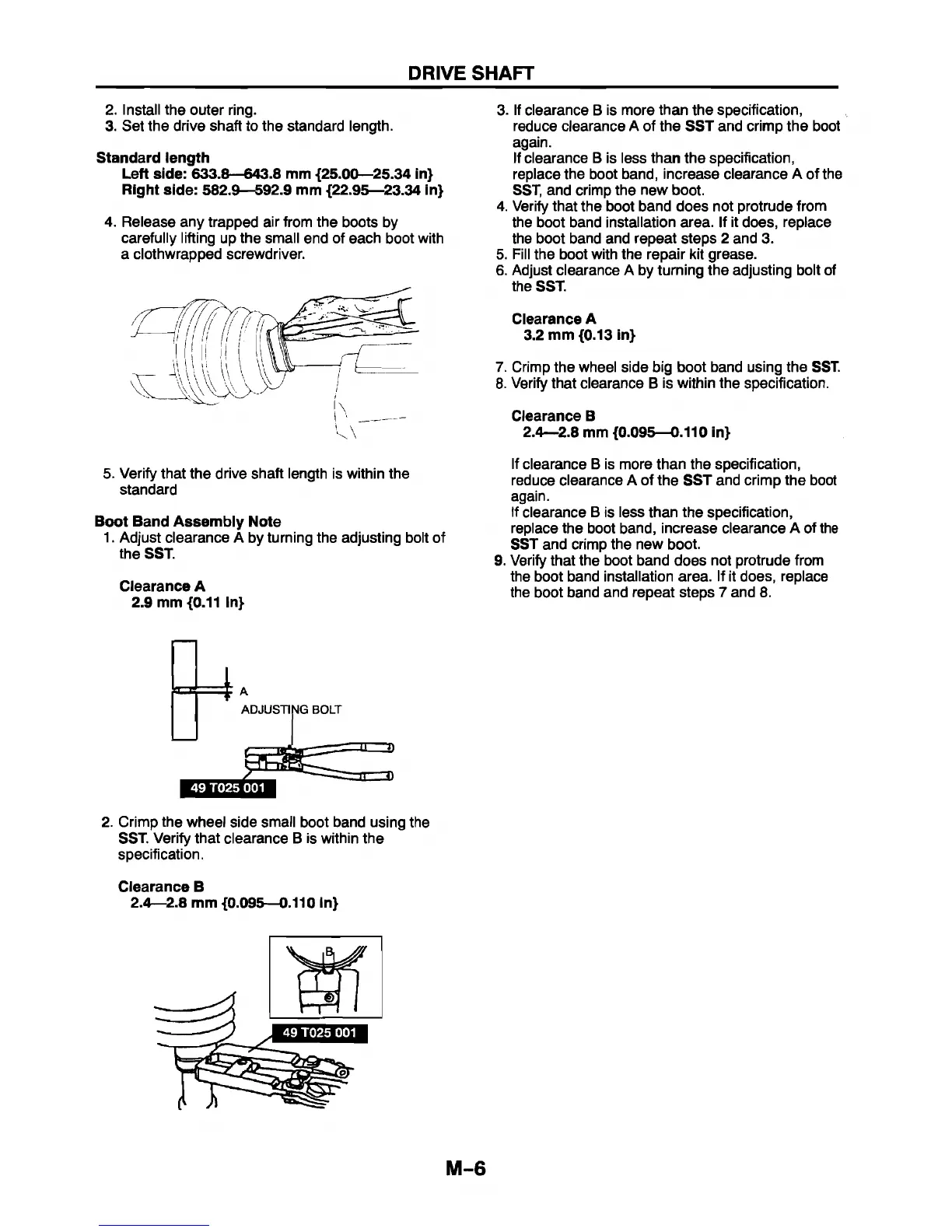
4. Release any trapped air from the boots by
carefully lifting up the small end of each boot with
a clothwrapped screwdriver.
5. Verify that the drive shaft length is within the
standard
Boot Band Assembly Note
1. Adjust clearance A by turning the adjusting bolt of
the SST.
Clearance A
2.9 mm {0.11 in}
3. If clearance B Is more than the specification,
reduce clearance A of the SST and crimp the boot
again.
If clearance B is less than the specification,
replace the boot band, increase clearance A of the
SST, and crimp the new boot.
4. Verify that the boot band does not protrude from
the boot band installation area. If it does, replace
the boot band and repeat steps 2 and 3.
5. Fill the boot with the repair kit grease.
6. Adjust clearance A by turning the adjusting bolt of
the SST.
Clearance A
3.2 mm {0.13 in}
7. Crimp the wheel side big boot band using the SST.
8. Verify that clearance B is within the specification.
Clearance B
2.4—2.8 mm {0.095—0.110 in}
If clearance B is more than the specification,
reduce clearance A of the SST and crimp the boot
again.
If clearance B is less than the specification,
replace the boot band, increase clearance A of the
SST and crimp the new boot.
9. Verify that the boot band does not protrude from
the boot band installation area. If it does, replace
the boot band and repeat steps 7 and 8.
ADJUSTING BOLT
T
49 T025 001
1 = 3 )
2. Crimp the wheel side small boot band using the
SST. Verify that clearance B is within the
specification.
Clearance B
2.4—2.8 mm {0.095—0.110 In}
M-6