ON-BOARD DIAGNOSTIC
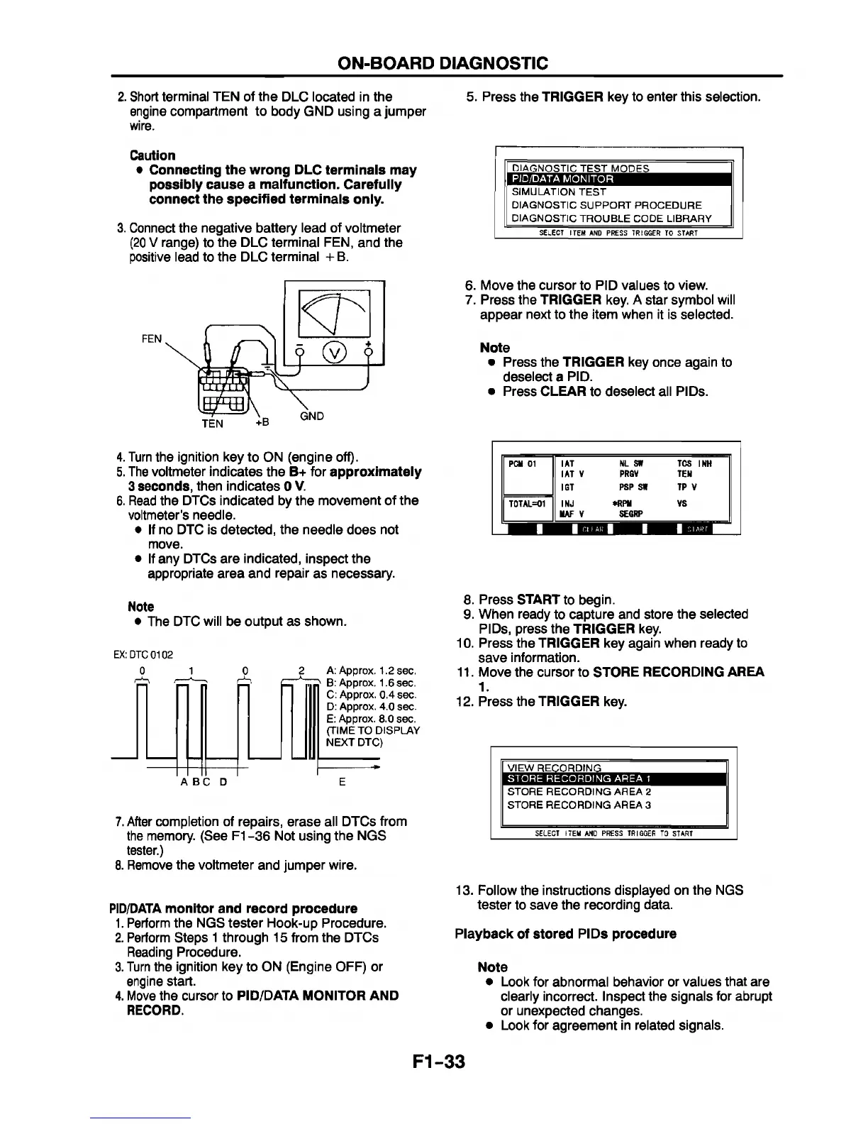
2. Short terminal TEN of the DLC located in the
engine compartment to body GND using a jumper
wire.
Caution
• Connecting the wrong DLC terminals may
possibly cause a malfunction. Carefully
connect the specified terminals only.
3. Connect the negative battery lead of voltmeter
(20 V range) to the DLC terminal FEN, and the
positive lead to the DLC terminal + B.
5. Press the TRIGGER key to enter this selection.
I
DIAGNOSTIC TEST MODES I
PID/DATA MONITOR
SIMULATION TEST
DIAGNOSTIC SUPPORT PROCEDURE
DIAGNOSTIC TROUBLE CODE LIBRARY
s e l ec t it e m a n d p r e s s t r ig g e r t o s t a rt
6. Move the cursor to PID values to view.
7. Press the TRIGGER key. A star symbol will
appear next to the item when it is selected.
Note
• Press the TRIGGER key once again to
deselect a PID.
• Press CLEAR to deselect all PIDs.
4. Turn the ignition key to ON (engine off).
5. The voltmeter indicates the B+ for approximately
3 seconds, then indicates 0 V.
6. Read the DTCs indicated by the movement of the
voltmeter's needle.
• If no DTC is detected, the needle does not
move.
• If any DTCs are indicated, inspect the
appropriate area and repair as necessary.
Note
• The DTC will be output as shown.
EX: DTC 0102
0 1 0 2 A: Approx. 1.2 sec.
rn ^ n in ' B: Approx. 1.6 sec.
C: Approx. 0.4 sec.
D: Approx. 4.0 sec.
E: Approx. 8.0 sec.
(TIME TO DISPLAY
NEXT DTC)
A BC D E
7. After completion of repairs, erase all DTCs from
the memory. (See F1 -36 Not using the NGS
tester.)
8. Remove the voltmeter and jumper wire.
PID/DATA monitor and record procedure
1. Perform the NGS tester Hook-up Procedure.
2. Perform Steps 1 through 15 from the DTCs
Reading Procedure.
3. Turn the ignition key to ON (Engine OFF) or
engine start.
4. Move the cursor to PID/DATA MONITOR AND
RECORD.
PCM 01 IAT
NL SW TCS INH
IAT V
PRGV
TEN
IGT
PSP SW
TP V
T0TAL=O1
INJ
HAF V
*RPH
SE6RP
VS
I 1
| ci 1 ai;
1 1
1 si art
8. Press START to begin.
9. When ready to capture and store the selected
PIDs, press the TRIGGER key.
10. Press the TRIGGER key again when ready to
save information.
11. Move the cursor to STORE RECORDING AREA
1.
12. Press the TRIGGER key.
1 1
1 VIEW RECORDING 1
STORE RECORDING AREA 1
STORE RECORDING AHEA 2
STORE RECORDING AREA 3
| SELECT ITEM AND PRESS TRIGGER TO START
13. Follow the instructions displayed on the NGS
tester to save the recording data.
Playback of stored PIDs procedure
Note
• Look for abnormal behavior or values that are
clearly incorrect. Inspect the signals for abrupt
or unexpected changes.
• Look for agreement in related signals.
F1-33


 To Next Page