ON-BOARD DIAGNOSTIC
DTC P1345
Except for GF4A-EL Models
DTC P1345 CMP sensor circuit malfunction
DETECTION
CONDITION
If PCM does no receive input voltage from CMP sensor within 12 engine cycles, PCM determines that
CMP circuit has malfunction.
POSSIBLE
CAUSE
• CMP sensor malfunction
• Connector or terminal malfunction
• CMP sensor is dirty
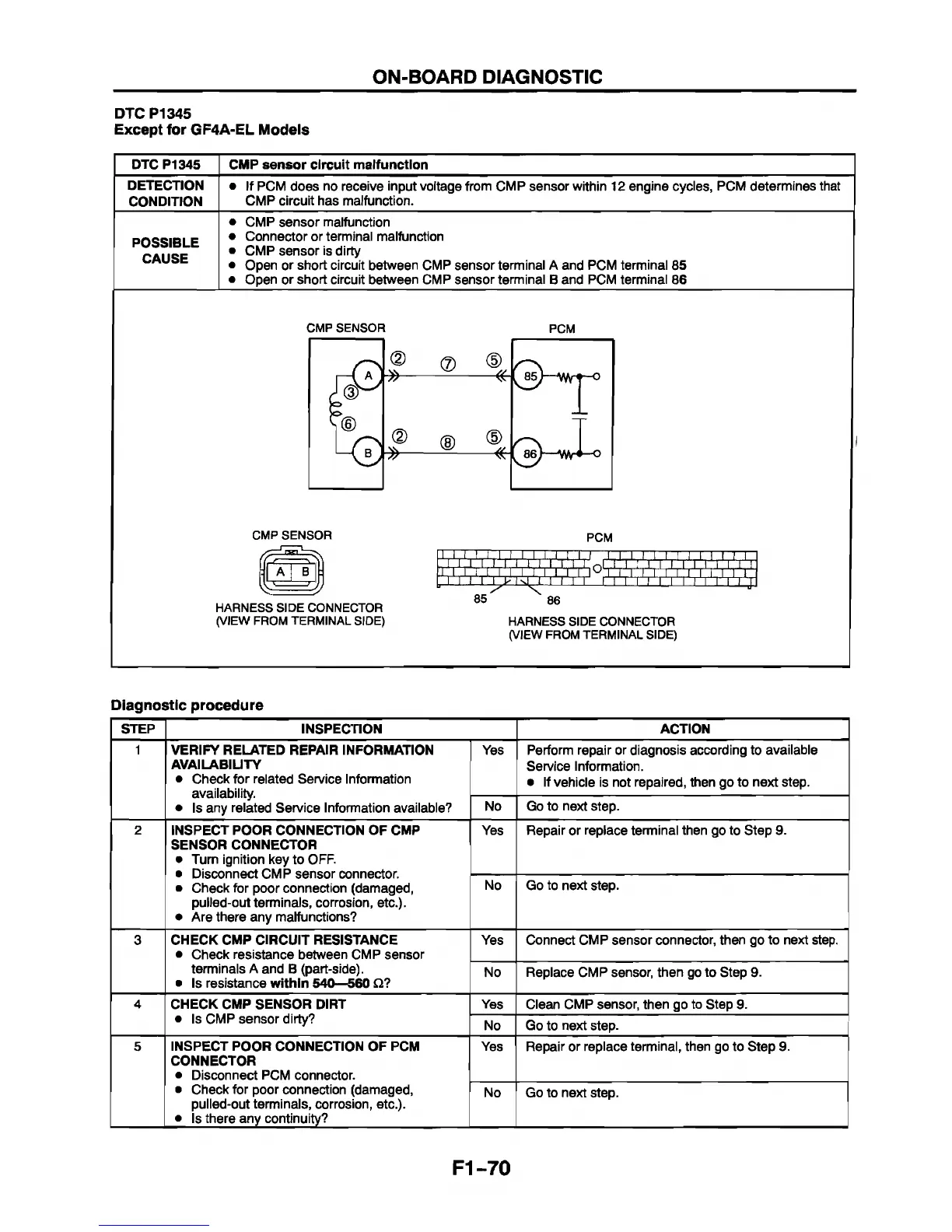
• Open or short circuit between CMP sensor terminal A and PCM terminal 85
• Open or short circuit between CMP sensor terminal B and PCM terminal 86
CMP SENSOR
PCM
CMP SENSOR
HARNESS SIDE CONNECTOR
(VIEW FROM TERMINAL SIDE)
PCM
111, I, I, I 11,1,1 ,1 ,1. I, I , I, I . I , I , I I. I. I I I I I I M ~
T
r r v L-'
85
86
HARNESS SIDE CONNECTOR
(VIEW FROM TERMINAL SIDE)
Diagnostic procedure
STEP INSPECTION ACTION
1
VERIFY RELATED REPAIR INFORMATION
AVAILABILITY
• Check for related Service Information
availability.
• Is any related Service Information available?
Yes Perform repair or diagnosis according to available
Sen/ice Information.
• If vehicle is not repaired, then go to next step.
No Go to next step.
2
INSPECT POOR CONNECTION OF CMP
SENSOR CONNECTOR
• Turn ignition key to OFF.
• Disconnect CMP sensor connector.
• Check for poor connection (damaged,
pulled-out terminals, corrosion, etc.).
• Are there any malfunctions?
Yes
Repair or replace terminal then go to Step 9.
No Go to next step.
3 CHECK CMP CIRCUIT RESISTANCE
• Check resistance between CMP sensor
terminals A and B (part-side).
• Is resistance within 540—560 £2?
Yes
Connect CMP sensor connector, then go to next step.
No Replace CMP sensor, then go to Step 9.
4
CHECK CMP SENSOR DIRT
• Is CMP sensor dirty?
Yes
Clean CMP sensor, then go to Step 9.
No Go to next step.
5 INSPECT POOR CONNECTION OF PCM
CONNECTOR
• Disconnect PCM connector.
• Check for poor connection (damaged,
pulled-out terminals, corrosion, etc.).
• Is there any continuity?
Yes Repair or replace terminal, then go to Step 9.
No Go to next step.
F1-70