TROUBLESHOOTING
Diagnostic procedure
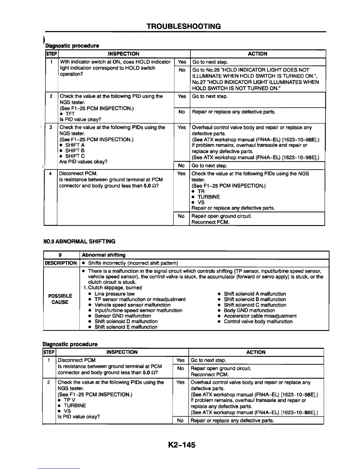
STEP INSPECTION ACTION
1 With indicator switch at ON, does HOLD indicator
light indication correspond to HOLD switch
operation?
Yes
Go to next step.
No Go to No.26 “HOLD INDICATOR LIGHT DOES NOT
ILLUMINATE WHEN HOLD SWITCH IS TURNED ON.”,
No.27 “HOLD INDICATOR LIGHT ILLUMINATES WHEN
HOLD SWITCH IS NOT TURNED ON.”
2
Check the value at the following PID using the
NGS tester.
(See F1-25 PCM INSPECTION.)
• TFT
Is PID value okay?
Yes Go to next step.
No Repair or replace any defective parts.
3 Check the value at the following PIDs using the
NGS tester.
(See F1-25 PCM INSPECTION.)
• SHIFT A
• SHIFT B
• SHIFT C
Are PID values okay?
Yes
Overhaul control valve body and repair or replace any
defective parts.
(See ATX workshop manual (FN4A-EL) [1623-10-98E].)
If problem remains, overhaul transaxle and repair or
replace any defective parts.
(See ATX workshop manual (FN4A-EL) [1623-10-98E].)
No Go to next step.
4
Disconnect PCM.
Is resistance between ground terminal at PCM
connector and body ground less than 5.0 Cl?
Yes
Check the value at the following PIDs using the NGS
tester.
(See F1-25 PCM INSPECTION.)
• TR
• TURBINE
• VS
Repair or replace any defective parts.
No Repair open ground circuit.
Reconnect PCM.
N0.9 ABNORMAL SHIFTING
9
Abnormal shifting
DESCRIPTION • Shifts incorrectly (incorrect shift pattern)
POSSIBLE
CAUSE
• There is a malfunction in the signal circuit which controls shifting (TP sensor, input/turbine speed sensor,
vehicle speed sensor), the control valve is stuck, the accumulator (forward or servo apply) is stuck, or the
clutch circuit is stuck.
1. Clutch slippage, burned
• Line pressure low • Shift solenoid A malfunction
• TP sensor malfunction or misadjustment • Shift solenoid B malfunction
• Vehicle speed sensor malfunction • Shift solenoid C malfunction
• Input/turbine speed sensor malfunction • Body GND malfunction
• Sensor GND malfunction • Accelerator cable misadjustment
• Shift solenoid D malfunction • Control valve body malfunction
• Shift solenoid E malfunction
Diagnostic procedure
STEP
INSPECTION
ACTION
1
Disconnect PCM
Is resistance between ground terminal at PCM
connector and body ground less than 5.0 £2?
Yes
Go to next step.
No
Repair open ground circuit.
Reconnect PCM.
2 Check the value at the following PIDs using the
NGS tester.
(See F1-25 PCM INSPECTION.)
• TPV
• TURBINE
• VS
Is PID value okay?
Yes Overhaul control valve body and repair or replace any
defective parts.
(See ATX workshop manual (FN4A-EL) [1623-10-98E].)
If problem remains, overhaul transaxle and repair or
replace any defective parts.
(See ATX workshop manual (FN4A-EL) [1623-10-98E].)
No Repair or replace any defective parts.
K2-145