HOW TO USE THIS MANUAL
Using the DTC troubleshooting flow
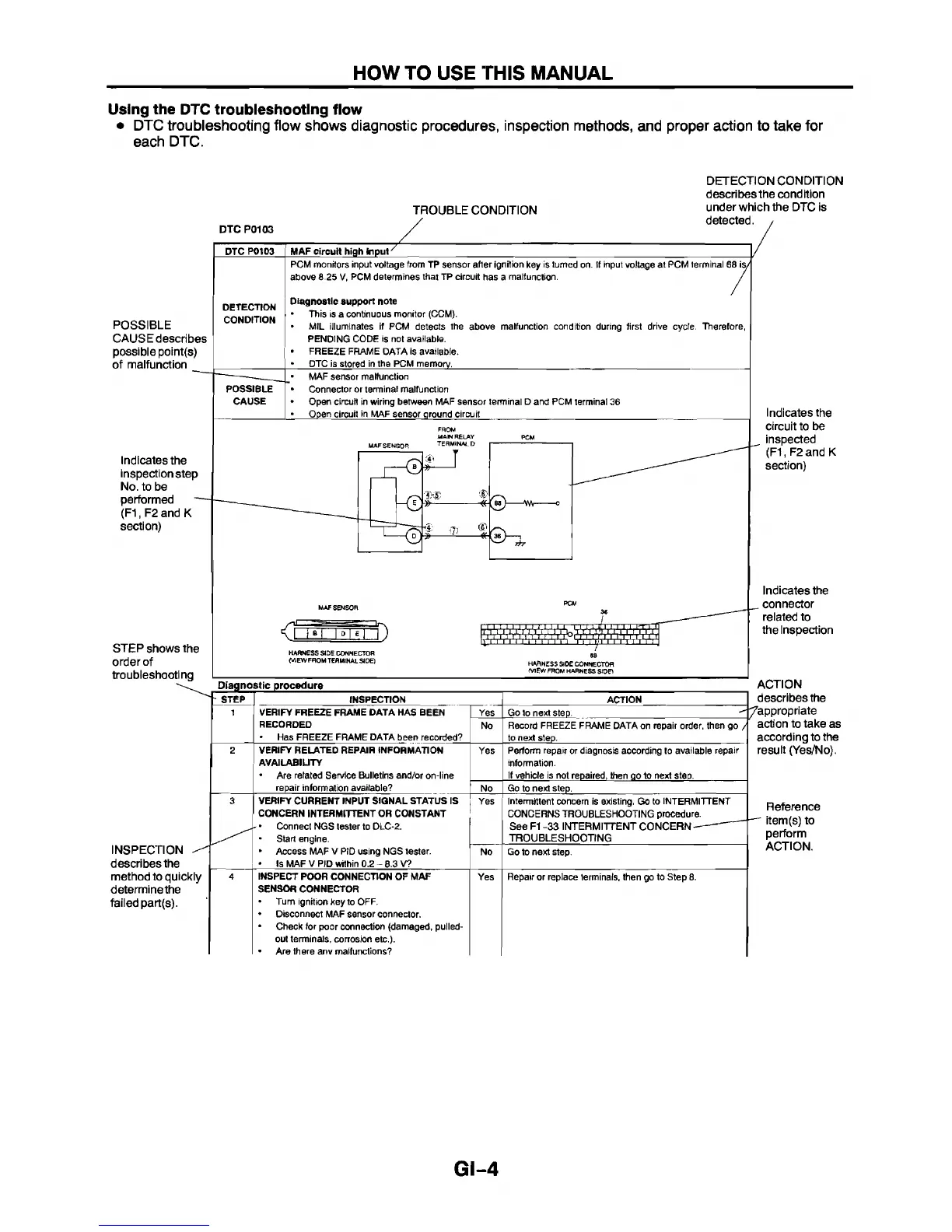
• DTC troubleshooting flow shows diagnostic procedures, inspection methods, and proper action to take for
each DTC.
TROUBLE CONDITION
DTC P0103
DETECTION CONDITION
describes the condition
under which the DTC is
detected. ,
PTC POI03
POSSIBLE
CAUSE describes
possible point(s)
of malfunction
DETECTION
CONDITION
Indicates the
inspection step
No. to be
performed
(F1, F2 and K
section)
POSSIBLE
CAUSE
MAF circuit high Input
/
PCM monitors input voltage from TP sensor after ignition key is turned on. If input voltage at PCM terminal 68 is/
above 8.25 V, PCM determines that TP circuit has a malfunction.
Diagnostic support note
This is a continuous monitor (CCM).
MIL illuminates if PCM detects the above malfunction condition during first drive cycle. Therefore,
PENDING CODE is not available.
FREEZE FRAME DATA is available.
DTC is stored in the PCM memory.
__________________________________________________________
MAF sensor malfunction
Connector or terminal malfunction
Open circuit in wiring between MAF sensor terminal D and PCM terminal 36
Open circuit in MAF sensor ground circuit
______________________________
Indicates the
circuit to be
inspected
(F1, F2and K
section)
STEP shows the
order of
troubleshooting
HARN ESS SIDE CONNECTOR
(V1EWFH0M TERMINAL SI DE)
HARN ESS SID E CONNECTOR
M E W FROM HA RNESS SID P
INSPECTION
describes the
method to quickly
determine the
failed part(s).
' ' STEP INSPECTION
ACTION
1 VERIFY FREEZE FRAME DATA HAS BEEN
RECORDED
Has FREEZE FRAME DATA been recorded?
Yes Go to next step.
No Record FREEZE FRAME DATA on repair order, then go /
to next steD.
2 VERIFY RELATED REPAIR INFORMATION
AVAILABILITY
• Are related Service Bulletins and/or on-line
repair information available?
Yes Perform repair or diagnosis according to available repair
information.
If vehicle is not repaired, then qo to next step.
No
Go to next step.
3 VERIFY CURRENT INPUT SIGNAL STATUS IS
CONCERN INTERMITTENT OR CONSTANT
- • Connect NGS tester to DLC-2.
Start engine.
* Access MAF V PID using NGS tester.
• Is MAF V PID within 0.2 - B.3 V?
Yes
Intermittent concern is existing. Go to INTERMITTENT
CONCERNS TROUBLESHOOTING procedure.
See F1 -33 INTERMITTENT CONCERN
-
----------
TROUBLESHOOTING
No
Go to next step.
4
INSPECT POOR CONNECTION OF MAF
SENSOR CONNECTOR
Turn ignition key to OFF.
• Disconnect MAF sensor connector.
• Check for poor connection (damaged, pulled-
out terminals, corrosion etc.).
• Are there anv malfunctions?
Yes
Repair or replace terminals, then go to Step 8.
Indicates the
. connector
related to
the Inspection
ACTION
describes the
^/appropriate
action to take as
according to the
result (Yes/No).
Reference
item(s) to
perform
ACTION.
GI-4