ON-BOARD DIAGNOSTIC
DTC P0118
Except for GF4A-EL Models
DTC P0118
ECT circuit high Input
DETECTION
CONDITION
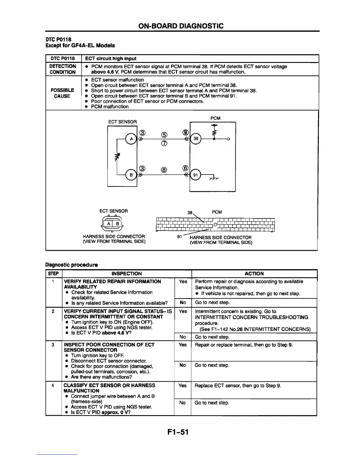
• PCM monitors ECT sensor signal at PCM terminal 38. If PCM detects ECT sensor voltage
above 4.6 V, PCM determines that ECT sensor circuit has malfunction.
POSSIBLE
CAUSE
ECT sensor malfunction
Open circuit between ECT sensor terminal A and PCM terminal 38.
Short to power circuit between ECT sensor terminal A and PCM terminal 38.
Open circuit between ECT sensor terminal B and PCM terminal 91.
Poor connection of ECT sensor or PCM connectors.
PCM malfunction
PCM
¥
(D (D ®
i O
* °
* ®
<D (D ©
77
ECT SENSOR
_ C I Q _
HARNESS SIDE CONNECTOR
(VIEW FROM TERMINAL SIDE)
38
PCM
W iÏ i'iÏ iÏ iV
r*r| 0fJI ! IM111 ! i 11 ! I V i ' f f î
r 11 ‘rV -f-1111111111111111 ^
91 HARNESS SIDE CONNECTOR
(VIEW FROM TERMINAL SIDE)
Diagnostic procedure
STEP INSPECTION ACTION
1
VERIFY RELATED REPAIR INFORMATION
AVAILABILITY
• Check for related Service Information
availability.
• Is any related Service Information available?
Yes
Perform repair or diagnosis according to available
Service Information.
• If vehicle is not repaired, then go to next step.
No Go to next step.
2 VERIFY CURRENT INPUT SIGNAL STATUS- IS
CONCERN INTERMITTENT OR CONSTANT
• Turn ignition key to ON (Engine OFF).
• Access ECT V PID using NGS tester.
• Is ECT V PID above 4.6 V?
Yes Intermittent concern is existing. Go to
INTERMITTENT CONCERN TROUBLESHOOTING
procedure.
(See F1-142 No.26 INTERM ITTENT CONCERNS)
No
Go to next step.
3 INSPECT POOR CONNECTION OF ECT
SENSOR CONNECTOR
• Turn ignition key to OFF.
• Disconnect ECT sensor connector.
• Check for poor connection (damaged,
pulled-out terminals, corrosion, etc.).
• Are there any malfunctions?
Yes Repair or replace terminal, then go to Step 9.
No Go to next step.
4
CLASSIFY ECT SENSOR OR HARNESS
MALFUNCTION
• Connect jumper wire between A and B
(harness-side)
• Access ECT V PID using NGS tester.
• Is ECT V PID approx. OV?
Yes Replace ECT sensor, then go to Step 9.
No Go to next step.
F1-51