WARNING AND INDICATOR SYSTEM
Diagnostic procedure
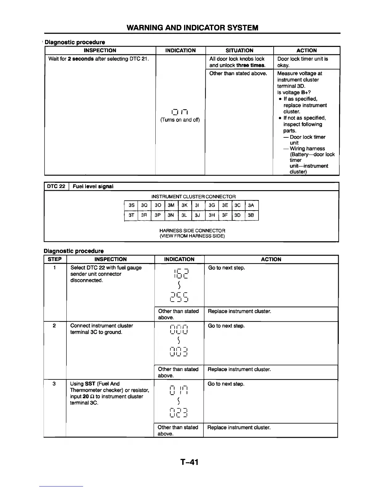
INSPECTION INDICATION SITUATION ACTION
Wait for 2 seconds after selecting DTC 21. All door lock knobs lock
and unlock three times.
Door lock timer unit is
okay.
C i n
(Turns on and off)
Other than stated above. Measure voltage at
instrument cluster
terminal 3D.
Is voltage B+?
• If as specified,
replace instrument
cluster.
• If not as specified,
inspect following
parts.
— Door lock timer
unit
— Wiring harness
(Battery—door lock
timer
unit—instrument
cluster)
DTC 22 Fuel level signal
INSTRUMENT CLUSTER CONNECTOR
3S 3Q 3 0 3M
3K
3I 3G 3E 3C 3A
3T 3R
3P
3N
3L 3J
3H 3F
3D 3B
.
HARNESS SIDE CONNECTOR
(VIEW FROM HARNESS SIDE)
Diagnostic procedure
STEP
INSPECTION INDICATION
ACTION
1
Select DTC 22 with fuel gauge
sender unit connector
disconnected.
II I
Il II
5
n i
i
___
i j
Go to next step.
Other than stated
above.
Replace instrument cluster.
2
Connect instrument cluster
terminal 3C to ground.
n n n
i n 11 i
s
M i l 1
U I J _i
Go to next step.
Other than stated
above.
Replace instrument cluster.
3 Using SST (Fuel And
Thermometer checker) or resistor,
input 20 i2 to instrument cluster
terminal 3C.
n i n
11 i i
i i i i
u i
___
i
Go to next step.
Other than stated
above.
Replace instrument cluster.
T-41


 To Next Page