ON-BOARD DIAGNOSTIC
11. Press the TRIGGER key.
12. Move the cursor to DIAGNOSTIC DATA LINK on
the main menu screen.
13. Press the TRIGGER key to enter into menu
system diagnostics.
I VEHICLE & ENGINE SELECTION I
DIAGNOSTIC DATA LINK
VIEW RECORDER AREAS
DIGITAL MEASUREMENT SYSTEM
NEW GENERATION STAR SETUP
SELECT ITEM AND P R ESS TRIGGER START
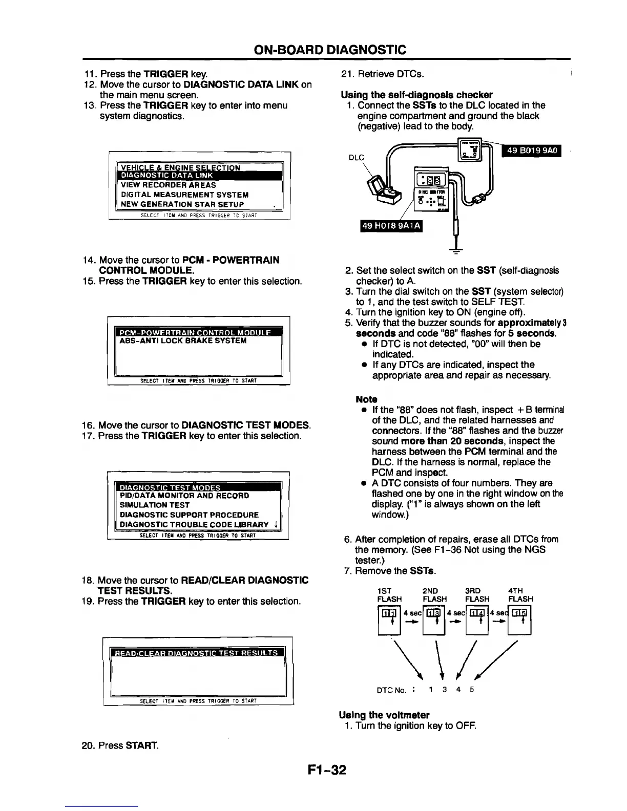
21. Retrieve DTCs.
Using the self-diagnosis checker
1. Connect the SSTs to the DLC located in the
engine compartment and ground the black
(negative) lead to the body.
14. Move the cursor to PCM - POWERTRAIN
CONTROL MODULE.
15. Press the TRIGGER key to enter this selection.
PCM -POWERTRAIN CONTROL MODULE
ABS-AN TI LOCK BRAKE SYSTEM
| SELECT ITEM AND PRESS TRIGGER TO START
16. Move the cursor to DIAGNOSTIC TEST MODES.
17. Press the TRIGGER key to enter this selection.
I I
DIAGNOSTIC TEST MODES
PID/OATA MONITOR AND RECORD
SIMULATION TEST
DIAGNOSTIC SUPPORT PROCEDURE
DIAGNOSTIC TROUBLE CODE LIBRARY I
| SELECT ITEM ANO PRESS TRIGGER TO START
18. Move the cursor to READ/CLEAR DIAGNOSTIC
TEST RESULTS.
19. Press the TRIGGER key to enter this selection.
HEAD/CLEAR DIAGNOSTIC TEST RESULTS
SELECT ITEM AND PRESS TRIGGER TO START
20. Press START.
2. Set the select switch on the SST (self-diagnosis
checker) to A.
3. Turn the dial switch on the SST (system selector)
to 1, and the test switch to SELF TEST.
4. Turn the ignition key to ON (engine off).
5. Verify that the buzzer sounds for
approximately 3
seconds and code “88” flashes for 5 seconds.
• If DTC is not detected, ”00” will then be
indicated.
• If any DTCs are indicated, inspect the
appropriate area and repair as necessary.
Note
• If the “88” does not flash, inspect + B terminal
of the DLC, and the related harnesses and
connectors. If the “88” flashes and the buzzer
sound more than 20 seconds, inspect the
harness between the PCM terminal and the
DLC. If the harness is normal, replace the
PCM and inspect.
• A DTC consists of four numbers. They are
flashed one by one in the right window on the
display. (“1” is always shown on the left
window.)
6. After completion of repairs, erase all DTCs from
the memory. (See F1-36 Not using the NGS
tester.)
7. Remove the SSTs.
1ST 2ND 3RD 4TH
FLASH FLASH FLASH FLASH
Using the voltmeter
1. Turn the ignition key to OFF.
F1-32
 Loading...


