AUTOMATIC TRANSAXLE
No. 1 Engine Mount Bolts Installation Note
Caution
• Misaligning the bolts may cause damage to
the bolt holes.
1. Use the SST (engine support) verify the
transaxle bolt holes and No. 1 engine mount
alignment.
2. Tighten the bolts to the specified torque.
Tightening torque
67—93 N-m {6.8—9.5 kgf-m, 50—68 ftlbf}
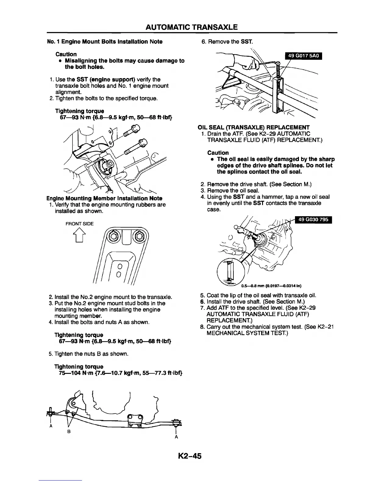
Engine Mounting Member Installation Note
1. Verify that the engine mounting rubbers are
installed as shown.
FRONT SIDE
2. Install the No.2 engine mount to the transaxle.
3. Put the No.2 engine mount stud bolts in the
installing holes when installing the engine
mounting member.
4. Install the bolts and nuts A as shown.
Tightening torque
67—93 N-m {6.8—9.5 kgf-m, 50—68 ft lbf}
5. Tighten the nuts B as shown.
Tightening torque
75—104 N-m {7.6—10.7 kgf-m, 55—77.3 ft lbf}
K2
6. Remove the SST.
OIL SEAL (TRANSAXLE) REPLACEMENT
1. Drain the ATF. (See K2-29 AUTOMATIC
TRANSAXLE FLUID (ATF) REPLACEMENT.)
Caution
• The oil seal is easily damaged by the sharp
edges of the drive shaft splines. Do not let
the splines contact the oil seal.
2. Remove the drive shaft. (See Section M.)
3. Remove the oil seal.
4. Using the SST and a hammer, tap a new oil seal
in evenly until the SST contacts the transaxle
case.
5. Coat the lip of the oil seal with transaxle oil.
6. Install the drive shaft. (See Section M.)
7. Add ATF to the specified level. (See K2-29
AUTOMATIC TRANSAXLE FLUID (ATF)
REPLACEMENT.)
8. Carry out the mechanical system test. (See K2-21
MECHANICAL SYSTEM TEST.)
45


 To Next Page