OUTLINE
OUTLINE
OUTLINE OF CONSTRUCTION
• The construction and operation of the suspension system of the face-lifted 626 (GF), 626 Station Wagon (GW)
is essentially the same as that of the current 626 (GF), 626 Station Wagon (GW) models. (See 626 Training
Manual 3303-10-97D, 626 Station Wagon Workshop Manual Supplement 1603-10-97K.)
FEATURES
Improved handling
• Revised steering gear mount bolt (10 mm {0.39 in}—»12 mm {0.47 in}) for improved rigidity
• Revised box-type transverse member
• Adopted stiffener in the installation part to the body of the shock absorber mount
• Adopted 16-inch wheels and 205/50R16 87V tires for FS (Hi-power) model
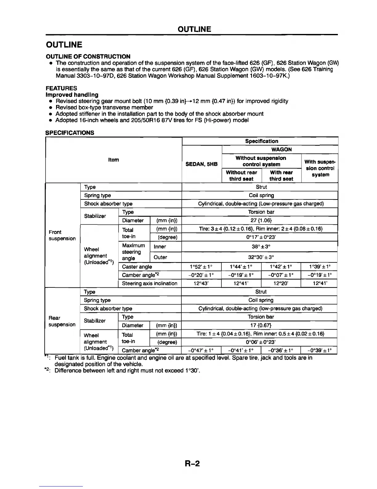
SPECIFICATIONS
Specification
WAGON
Item
SEDAN, 5HB
W ithout suspension
control system
W ith suspen
sion control
system
W ithout rear
th ird seat
W ith rear
th ird seat
Type Strut
Spring type
Coil spring
Shock absorber type
Cylindrical, double-acting (Low-pressure gas charged)
Stabilizer
Type
Torsion bar
Diameter
(mm {in}) 27 {1.06}
Front
suspension
Total
(mm {in})
Tire: 3 ± 4 {0 .12 ± 0 .16 }, Rim inner: 2± 4 {0 .08 ± 0 .16 }
toe-in
(degree) 0°17’ ±0 °23’
Wheel
Maximum
steering
angle
Inner 38°
±3°
alignment
(Unloaded*1)
Outer
32°30’ ± 3°
Caster angle
1°52’ ±1°
1°44'±1° 1°42’ ±1 °
1°39’ ±1°
Camber angle*2
-0°20’ ± 1°
-0°19’ ±1 °
-0°0 7'± 1 °
-0°19’ ±1°
Steering axis inclination 12°43’
12°41’
12°20’
12°41 '
Type
Strut
Spring type Coil spring
Shock absorber type Cylindrical, double-acting (low-pressure gas charged)
Rear
Stabilizer
Type
Torsion bar
suspension
Diameter (mm {in})
17 {0.67}
Wheel
Total
(mm {in})
Tire: 1 ± 4 {0.04 ±0.16}, Rim inner: 0.5 ± 4 {0.02 ±0.16}
alignment
toe-in
(degree)
0°06' ± 0°23’
(Unloaded*1)
Camber angle*2
-0°47’ ±1°
-0°41’ ± 1 °
-0°36’ ±1 °
-0°39'±1°
1: Fuel tank is full. Engine coolant and engine oil are at specified level. Spare tire, jack and tools are in
designated position of the vehicle.
*2: Difference between left and right must not exceed 1 °30\
R-2


 To Next Page