ON-BOARD DIAGNOSTIC SYSTEM
OUTLINE
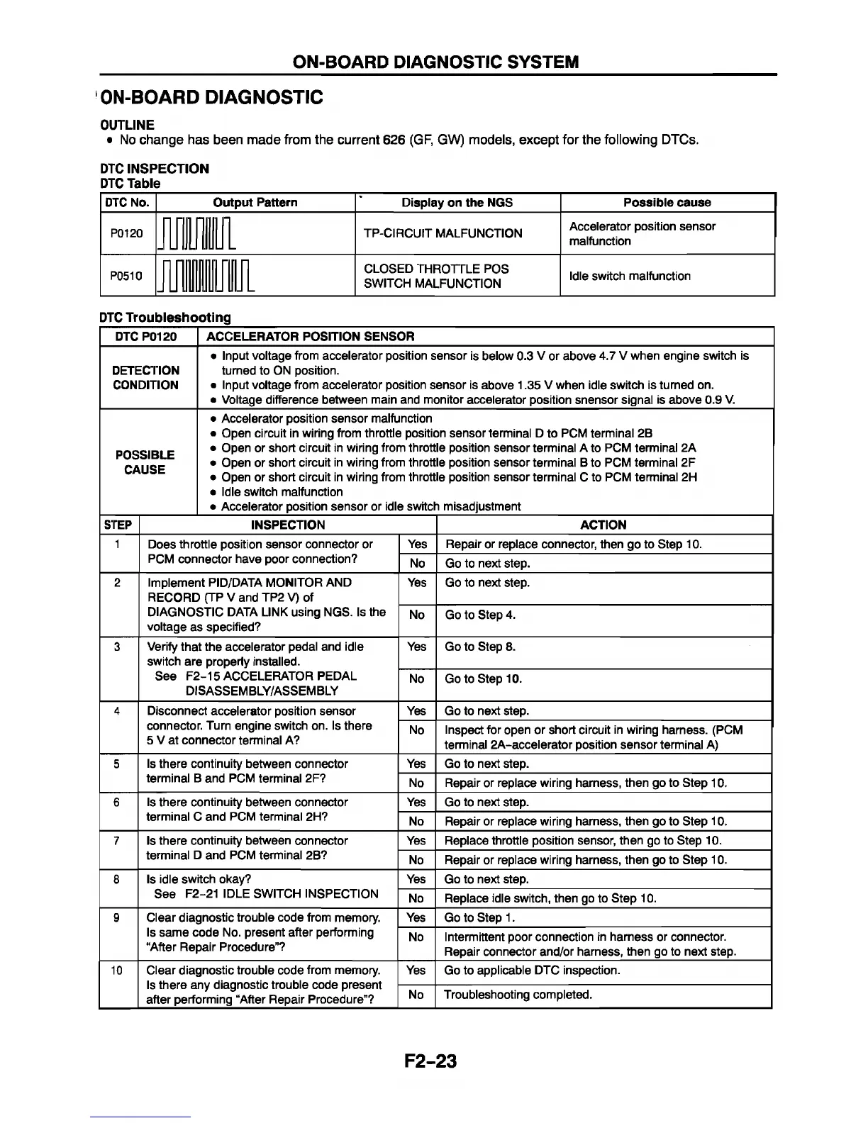
• No change has been made from the current 626 (GF, GW) models, except for the following DTCs.
ON-BOARD DIAGNOSTIC
DTC INSPECTION
DTC Table
DTC No.
Output Pattern
Display on the NGS
Possible cause
P0120
TP-CIRCUIT MALFUNCTION
Accelerator position sensor
malfunction
P0510
CLOSED THROrrLE POS
SWITCH MALFUNCTION
Idle switch malfunction
?TC Troubleshooting
DTC P0120
ACCELERATOR POSITION SENSOR
DETECTION
CONDITION
• Input voltage from accelerator position sensor is below 0.3 V or above 4.7 V when engine switch is
turned to ON position.
• Input voltage from accelerator position sensor is above 1.35 V when idle switch is turned on.
• Voltage difference between main and monitor accelerator position snensor signal is above 0.9 V.
POSSIBLE
CAUSE
• Accelerator position sensor malfunction
• Open circuit in wiring from throttle position sensor terminal D to PCM terminal 2B
• Open or short circuit in wiring from throttle position sensor terminal A to PCM terminal 2A
• Open or short circuit in wiring from throttle position sensor terminal B to PCM terminal 2F
• Open or short circuit in wiring from throttle position sensor terminal C to PCM terminal 2H
• Idle switch malfunction
• Accelerator position sensor or idle switch misadjustment
STEP INSPECTION ACTION
1
Does throttle position sensor connector or
PCM connector have poor connection?
Yes Repair or replace connector, then go to Step 10.
No Go to next step.
2
Implement PID/DATA MONITOR AND
RECORD (TP V and TP2 V) of
DIAGNOSTIC DATA LINK using NGS. Is the
voltage as specified?
Yes Go to next step.
No Go to Step 4.
3 Verify that the accelerator pedal and idle
switch are properly installed.
See F2-15 ACCELERATOR PEDAL
DISASSEMBLY/ASSEMBLY
Yes Go to Step 8.
No Go to Step 10.
4 Disconnect accelerator position sensor
connector. Turn engine switch on. Is there
5 V at connector terminal A?
Yes Go to next step.
No
Inspect for open or short circuit in wiring harness. (PCM
terminal 2A-accelerator position sensor terminal A)
5
Is there continuity between connector
terminal B and PCM terminal 2F?
Yes Go to next step.
No
Repair or replace wiring harness, then go to Step 10.
6
Is there continuity between connector
terminal C and PCM terminal 2H?
Yes Go to next step.
No Repair or replace wiring harness, then go to Step 10.
7 Is there continuity between connector
terminal D and PCM terminal 2B?
Yes Replace throttle position sensor, then go to Step 10.
No Repair or replace wiring harness, then go to Step 10.
8
Is idle switch okay?
See F2-21 IDLE SWITCH INSPECTION
Yes Go to next step.
No Replace idle switch, then go to Step 10.
9
Clear diagnostic trouble code from memory.
Is same code No. present after performing
“After Repair Procedure”?
Yes Go to Step 1.
No
Intermittent poor connection in harness or connector.
Repair connector and/or harness, then go to next step.
10 Clear diagnostic trouble code from memory.
Is there any diagnostic trouble code present
after performing “After Repair Procedure”?
Yes Go to applicable DTC inspection.
No
Troubleshooting completed.
F2-23


 To Next Page