CONTROL SYSTEM
CONTROL SYSTEM
PCM INSPECTION
Except for GF4A-EL models
Using SSTs (NGS tester)
Note
• PIDs for the following parts are not available
on this model. Go to the appropriate part
inspection page.
— Water temperature sender unit (Integrated
with ECT sensor)
(See Section F.)
— CMP sensor (See Section F.)
— Main relay (See Section F.)
1. Connect the SSTs (NGS tester) to the DLC. (See
F1-30 NGS tester hook-up procedure.)
2. Turn the ignition key to ON (Engine OFF).
3. Select the “PID/DATA MONITOR AND RECORD”
function on the NGS tester display and press
TRIGGER. (See F1-33 PID/DATA monitor and
record procedure.)
4. Select the appropriate PID on the NGS tester
display and press START.
5. Measure the PID value.
• If PID value is not within the specification,
follow the instruction in Action column.
Note
The PID/DATA MONITOR function monitors
the calculated value of the input/output signals
in the PCM. Therefore, an output device
malfunction is not directly indicated as a
malfunction of the monitored value for the
output device. If a monitored value of an
output device is out of specification, inspect
the monitored value of the input device related
to the output control.
For input/output signals except those of the
monitoring items, use a voltmeter to measure
the PCM terminal voltage.
When measuring the following PID value,
perform the following:
— TP V PID at Constant Voltage Terminal
Inspection.
Perform the SIMULATION TEST for the output
device (A/C RLY, FP RLY, FAN2, FAN3, IACV,
INJ, PRCV, PRGV, VICSV) after PID/DATA
measurement is completed.
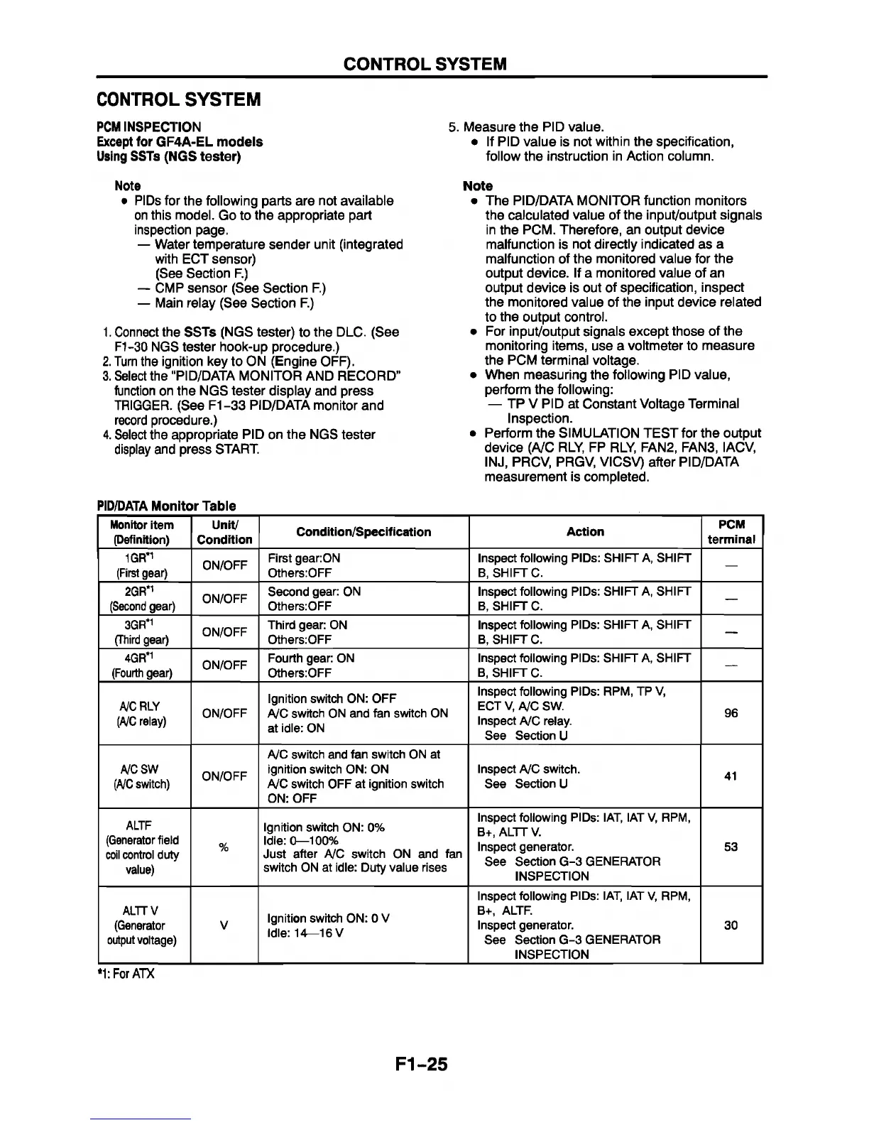
PID/DATA Monitor Table
Monitor item
(Definition)
Unit/
Condition
Condition/Specification
Action
PCM
terminal
1GR*1
(First gear)
ON/OFF
First gear:ON
Others:OFF
Inspect following PIDs: SHIFT A, SHIFT
B, SHIFT C.
2GR*1
(Second gear)
ON/OFF
Second gear: ON
Others:OFF
Inspect following PIDs: SHIFT A, SHIFT
B, SHIFT C.
-
3GR*1
(Third gear)
ON/OFF
Third gear: ON
Others:OFF
Inspect following PIDs: SHIFT A, SHIFT
B, SHIFT C.
—
4GR*1
(Fourth gear)
ON/OFF
Fourth gear: ON
Others:OFF
Inspect following PIDs: SHIFT A, SHIFT
B, SHIFT C.
—
A/C RLY
(A/C relay)
ON/OFF
Ignition switch ON: OFF
A/C switch ON and fan switch ON
at idle: ON
Inspect following PIDs: RPM, TP V,
ECT V, A/C SW.
Inspect A/C relay.
See Section U
96
A/CSW
(A/C switch)
ON/OFF
A/C switch and fan switch ON at
ignition switch ON: ON
A/C switch OFF at ignition switch
ON: OFF
Inspect A/C switch.
See Section U
41
ALTF
(Generator field
coil control duty
value)
%
Ignition switch ON: 0%
Idle: 0—100%
Just after A/C switch ON and fan
switch ON at idle: Duty value rises
Inspect following PIDs: IAT, IAT V, RPM,
B+, ALTT V.
Inspect generator.
See Section G-3 GENERATOR
INSPECTION
53
ALTTV
(Generator
output voltage)
V
Ignition switch ON: 0 V
Idle: 14—16 V
Inspect following PIDs: IAT, IAT V, RPM,
B+, ALTF.
Inspect generator.
See Section G-3 GENERATOR
INSPECTION
30
*1: For ATX
F1-25
 Loading...


