WARNING AND INDICATOR SYSTEM
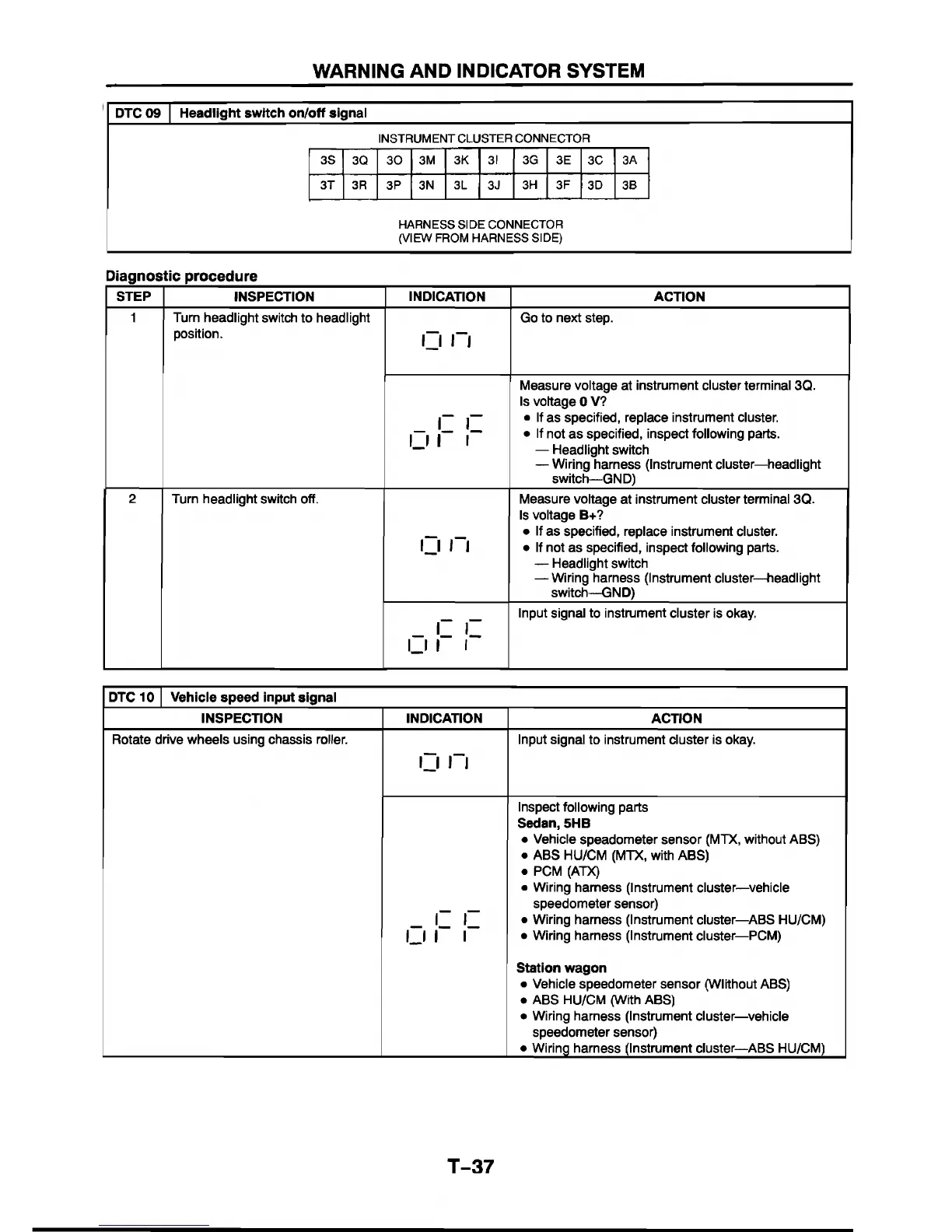
DTC 09 Headlight switch on/off signal
INSTRUMENT CLUSTER CONNECTOR
3S 3Q
30
3M 3K 31 3G 3E
3C
3A
3T 3R
3P
3N 3L
3J
3H 3F
3D 3B
HARNESS SIDE CONNECTOR
(VIEW FROM HARNESS SIDE)
Diagnostic procedure
STEP
INSPECTION INDICATION ACTION
1
Turn headlight switch to headlight
position.
I J n
Go to next step.
r r
i_ i I I
Measure voltage at instrument cluster terminal 3Q.
Is voltage 0 V?
■ If as specified, replace instrument cluster.
• If not as specified, inspect following parts.
— Headlight switch
— Wiring harness (Instrument cluster—headlight
switch—GND)
2
Turn headlight switch off.
C i r i
Measure voltage at instrument cluster terminal 3Q.
Is voltage B+?
• If as specified, replace instrument cluster.
• If not as specified, inspect following parts.
— Headlight switch
— Wiring harness (Instrument cluster—headlight
switch—GND)
r r
i_i I
r
Input signal to instrument cluster is okay.
DTC 10 Vehicle speed input signal
INSPECTION INDICATION
ACTION
Rotate drive wheels using chassis roller.
I J n
Input signal to instrument cluster is okay.
r r
U I I
Inspect following parts
Sedan, 5HB
• Vehicle speadometer sensor (MTX, without ABS)
• ABS HU/CM (MTX, with ABS)
• PCM (ATX)
• Wiring harness (Instrument cluster—vehicle
speedometer sensor)
• Wiring harness (Instrument cluster—ABS HU/CM)
• Wiring harness (Instrument cluster—PCM)
Station wagon
• Vehicle speedometer sensor (Wlithout ABS)
• ABS HU/CM (With ABS)
• Wiring harness (Instrument cluster—vehicle
speedometer sensor)
• Wiring harness (Instrument cluster—ABS HU/CM)
T-37


 To Next Page