ON-BOARD DIAGNOSTIC
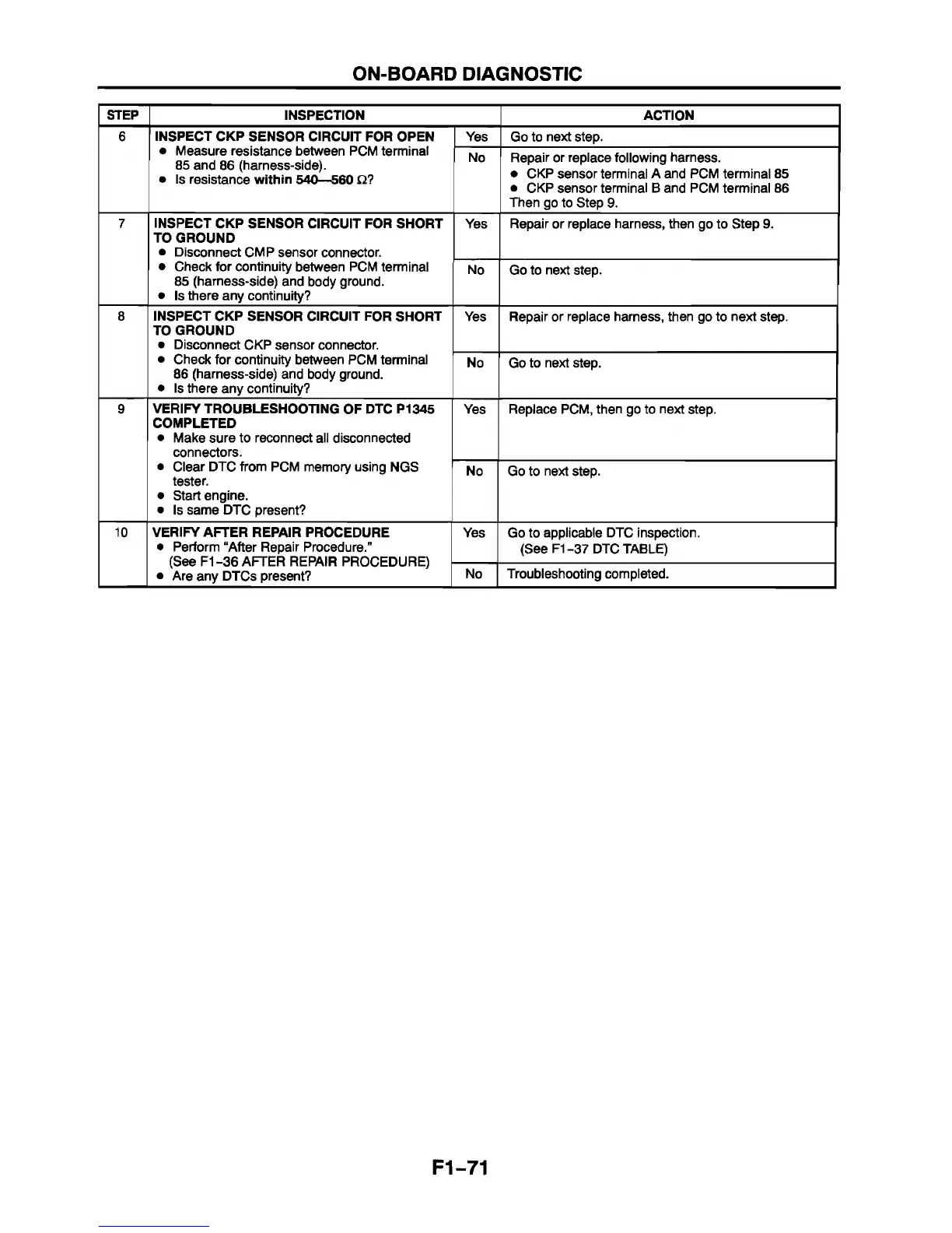
STEP
INSPECTION ACTION
6 INSPECT CKP SENSOR CIRCUIT FOR OPEN
• Measure resistance between PCM terminal
85 and 86 (harness-side).
• Is resistance within 540—560 £2?
Yes Go to next step.
No
Repair or replace following harness.
• CKP sensor terminal A and PCM terminal 85
• CKP sensor terminal B and PCM terminal 86
Then go to Step 9.
7
INSPECT CKP SENSOR CIRCUIT FOR SHORT
TO GROUND
• Disconnect CMP sensor connector.
• Check for continuity between PCM terminal
85 (harness-side) and body ground.
• Is there any continuity?
Yes Repair or replace harness, then go to Step 9.
No Go to next step.
8
INSPECT CKP SENSOR CIRCUIT FOR SHORT
TO GROUND
• Disconnect CKP sensor connector.
• Check for continuity between PCM terminal
86 (harness-side) and body ground.
• Is there any continuity?
Yes Repair or replace harness, then go to next step.
No Go to next step.
9 VERIFY TROUBLESHOOTING OF DTC P1345
COMPLETED
• Make sure to reconnect all disconnected
connectors.
• Clear DTC from PCM memory using NGS
tester.
• Start engine.
• Is same DTC present?
Yes
Replace PCM, then go to next step.
No Go to next step.
10
VERIFY AFTER REPAIR PROCEDURE
• Perform “After Repair Procedure.”
(See F1 -36 AFTER REPAIR PROCEDURE)
• Are any DTCs present?
Yes Go to applicable DTC inspection.
(See F1-37 DTC TABLE)
No
Troubleshooting completed.
F1-71



 To Next Page