ON-BOARD DIAGNOSTIC
STEP INSPECTION
ACTION
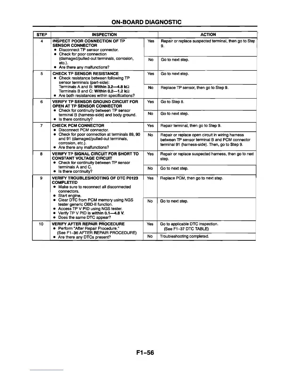
4 INSPECT POOR CONNECTION OF TP
SENSOR CONNECTOR
• Disconnect TP sensor connector.
• Check for poor connection
(damaged/pulled-out terminals, corrosion,
etc.).
• Are there any malfunctions?
Yes Repair or replace suspected terminal, then go to Step
9.
No
Go to next step.
5 CHECK TP SENSOR RESISTANCE
• Check resistance between following TP
sensor terminals (part-side):
Terminals A and B: Within 3.2—4.8 k ii
Terminals B and C: Within 0.2—1.2 ki2
• Are both resistances within specifications?
Yes
Go to next step.
No Replace TP sensor, then go to Step 9.
6 VERIFY TP SENSOR GROUND CIRCUIT FOR
OPEN AT TP SENSOR CONNECTOR
• Check for continuity between TP sensor
terminal B (harness-side) and body ground.
• Is there continuity?
Yes Go to Step 8.
No Go to next step.
7
CHECK PCM CONNECTOR
• Disconnect PCM connector.
• Check for poor connection at terminals 89, 90
and 91 (damaged/pulled-out terminals,
corrosion, etc.).
• Are there any malfunctions?
Yes Repair terminal, then go to Step 9.
No
Repair or replace open circuit in wiring harness
between TP sensor terminal B and PCM connector
terminal 91 (harness-side). Then, go to Step 9.
8 VERIFY TP SIGNAL CIRCUIT FOR SHORT TO
CONSTANT VOLTAGE CIRCUIT
• Check for continuity between TP sensor
terminals A and C.
• Is there continuity?
Yes
Repair or replace suspected harness, then go to next
step.
No Go to next step.
9 VERIFY TROUBLESHOOTING OF DTC P0123
COMPLETED
• Make sure to reconnect all disconnected
connectors.
• Start engine.
• Clear DTC from PCM memory using NGS
tester generic OBD-II function.
• Access TP V PID using NGS tester.
• Verify TP V PID is
within 0.1—4.8 V.
• Does the same DTC appear?
Yes
Replace PCM, then go to next step.
No Go to next step.
10
VERIFY AFTER REPAIR PROCEDURE
• Perform “After Repair Procedure.”
(See F1-36 AFTER REPAIR PROCEDURE)
• Are there any DTCs present?
Yes
Go to applicable DTC inspection.
(See F1-37 DTC TABLE)
No
Troubleshooting completed.
F1-56
 Loading...


