ON-BOARD DIAGNOSTIC
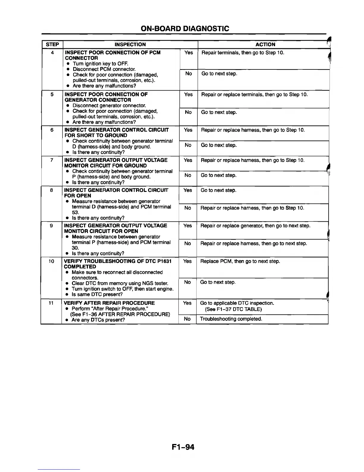
STEP INSPECTION | ACTION rj
4
INSPECT POOR CONNECTION OF PCM
CONNECTOR
• Turn ignition key to OFF.
• Disconnect PCM connector.
• Check for poor connection (damaged,
pulled-out terminals, corrosion, etc.).
• Are there any malfunctions?
Yes Repair terminals, then go to Step 10. j
1
No Go to next step.
5 INSPECT POOR CONNECTION OF
GENERATOR CONNECTOR
• Disconnect generator connector.
• Check for poor connection (damaged,
pulled-out terminals, corrosion, etc.).
• Are there any malfunctions?
Yes Repair or replace terminals, then go to Step 10.
No
Go to next step.
6 INSPECT GENERATOR CONTROL CIRCUIT
FOR SHORT TO GROUND
• Check continuity between generator terminal
D (harness-side) and body ground.
• Is there any continuity?
Yes Repair or replace harness, then go to Step 10.
No
Go to next step.
7
INSPECT GENERATOR OUTPUT VOLTAGE
MONITOR CIRCUIT FOR GROUND
• Check continuity between generator terminal
P (harness-side) and body ground.
• Is there any continuity?
Yes Repair or replace harness, then go to Step 10.
r
No Go to next step. |
8 INSPECT GENERATOR CONTROL CIRCUIT
FOR OPEN
• Measure resistance between generator
terminal D (harness-side) and PCM terminal
53.
• Is there any continuity?
Yes Go to next step.
No
Repair or replace harness, then go to Step 10.
9 INSPECT GENERATOR OUTPUT VOLTAGE
MONITOR CIRCUIT FOR OPEN
• Measure resistance between generator
terminal P (harness-side) and PCM terminal
30.
• Is there any continuity?
Yes Repair or replace generator, then go to next step.
il
No Repair or replace harness, then go to next step.
10 VERIFY TROUBLESHOOTING OF DTC P1631
COMPLETED
• Make sure to reconnect all disconnected
connectors.
• Clear DTC from memory using NGS tester.
• Turn ignition switch to OFF, then start engine.
• Is same DTC present?
Yes Replace PCM, then go to next step.
No Go to next step.
j
11
VERIFY AFTER REPAIR PROCEDURE
• Perform “After Repair Procedure.”
(See F1-36 AFTER REPAIR PROCEDURE)
• Are any DTCs present?
Yes Go to applicable DTC inspection. ’
(See F1-37 DTC TABLE)
No
Troubleshooting completed.
F1-94


 To Next Page