AUTOMATIC TRANSAXLE
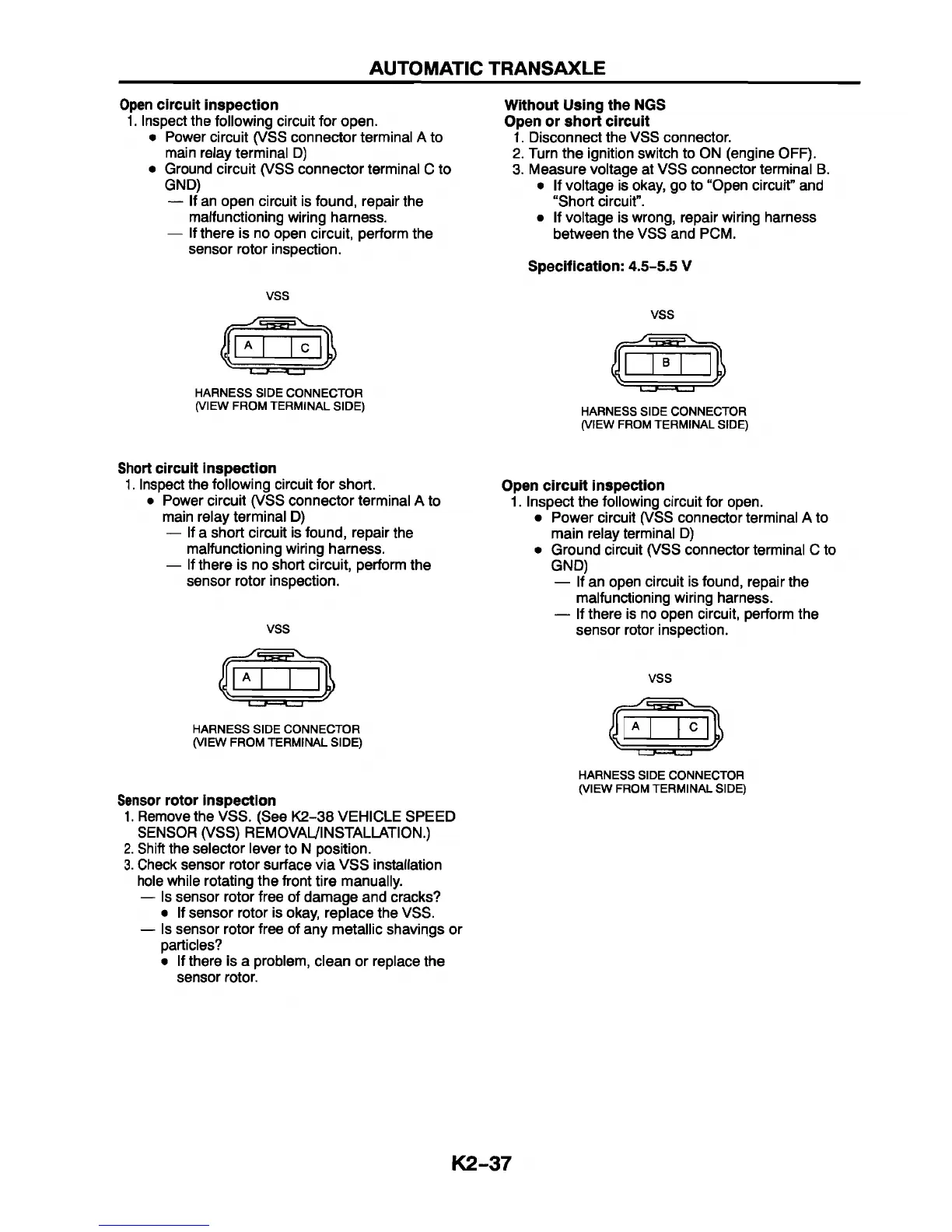
Open circuit inspection
1. Inspect the following circuit for open.
• Power circuit (VSS connector terminal A to
main relay terminal D)
• Ground circuit (VSS connector terminal C to
GND)
— If an open circuit is found, repair the
malfunctioning wiring harness.
— If there is no open circuit, perform the
sensor rotor inspection.
VSS
HARNESS SIDE CONNECTOR
(VIEW FROM TERMINAL SIDE)
Without Using the NGS
Open or short circuit
1. Disconnect the VSS connector.
2. Turn the ignition switch to ON (engine OFF).
3. Measure voltage at VSS connector terminal B.
• If voltage is okay, go to “Open circuit” and
“Short circuit”.
• If voltage is wrong, repair wiring harness
between the VSS and PCM.
Specification: 4.5-S.5 V
VSS
HARNESS SIDE CONNECTOR
(VIEW FROM TERMINAL SIDE)
Short circuit inspection
1. Inspect the following circuit for short.
• Power circuit (VSS connector terminal A to
main relay terminal D)
— If a short circuit is found, repair the
malfunctioning wiring harness.
— If there is no short circuit, perform the
sensor rotor inspection.
VSS
HARNESS SIDE CONNECTOR
(VIEW FROM TERMINAL SIDE)
Sensor rotor inspection
1. Remove the VSS. (See K2-38 VEHICLE SPEED
SENSOR (VSS) REMOVAL/INSTALLATION.)
2. Shift the selector lever to N position.
3. Check sensor rotor surface via VSS installation
hole while rotating the front tire manually.
— Is sensor rotor free of damage and cracks?
• If sensor rotor is okay, replace the VSS.
— Is sensor rotor free of any metallic shavings or
particles?
• If there is a problem, clean or replace the
sensor rotor.
Open circuit inspection
1. Inspect the following circuit for open.
• Power circuit (VSS connector terminal A to
main relay terminal D)
• Ground circuit (VSS connector terminal C to
GND)
— If an open circuit is found, repair the
malfunctioning wiring harness.
— If there is no open circuit, perform the
sensor rotor inspection.
VSS
HARNESS SIDE CONNECTOR
(VIEW FROM TERMINAL SIDE)
K2-37