ON-BOARD DIAGNOSTIC
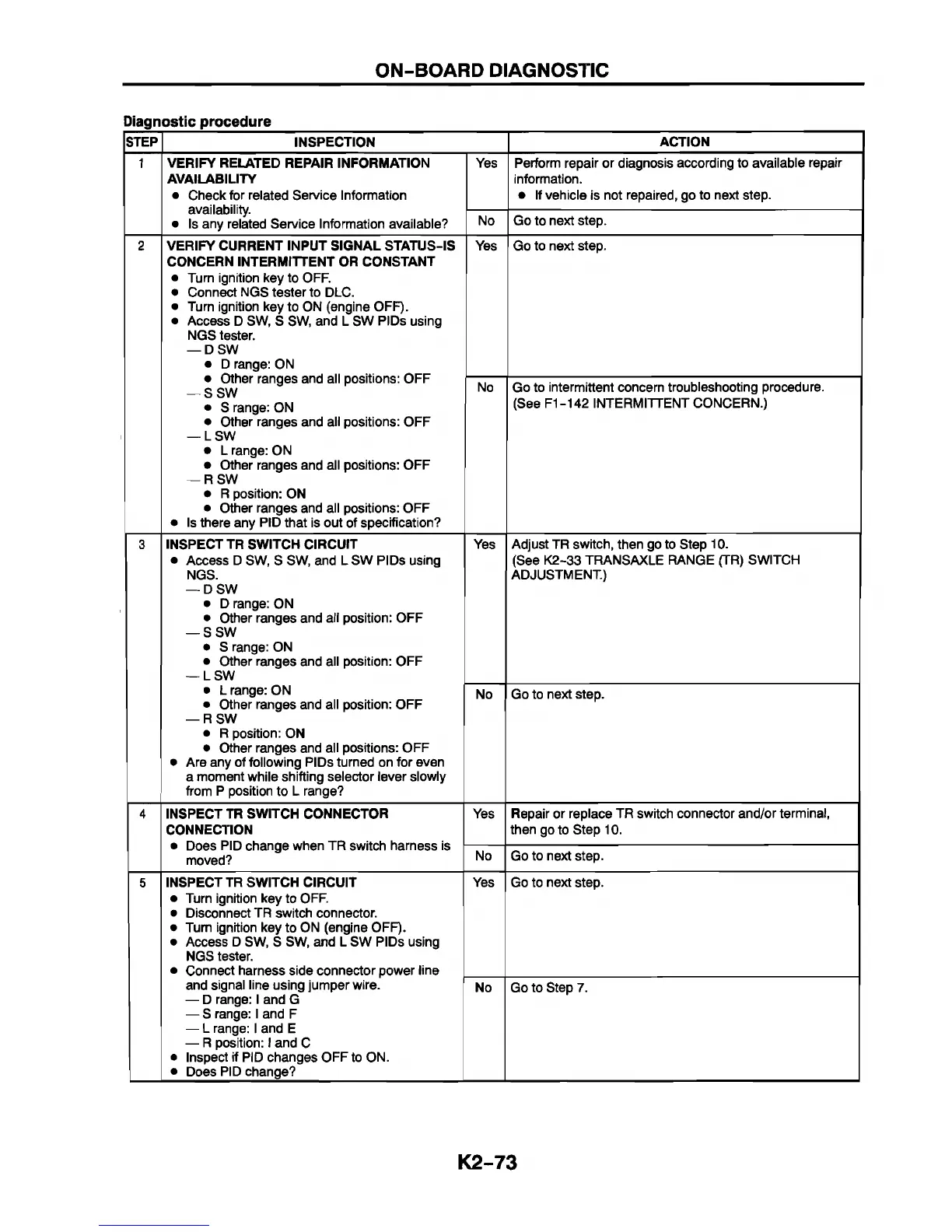
Diagnostic procedure
STEP
INSPECTION
ACTION
1 VERIFY RELATED REPAIR INFORMATION
AVAILABILITY
• Check for related Service Information
availability.
• Is any related Service Information available?
Yes
Perform repair or diagnosis according to available repair
information.
• If vehicle is not repaired, go to next step.
No
Go to next step.
2 VERIFY CURRENT INPUT SIGNAL STATUS-IS
CONCERN INTERMITTENT OR CONSTANT
• Turn ignition key to OFF.
• Connect NGS tester to DLC.
• Turn ignition key to ON (engine OFF).
• Access D SW, S SW, and L SW PIDs using
NGS tester.
— DSW
• D range: ON
• Other ranges and all positions: OFF
— SSW
• S range: ON
• Other ranges and all positions: OFF
— LSW
• L range: ON
• Other ranges and all positions: OFF
— RSW
• R position: ON
• Other ranges and all positions: OFF
• Is there any PID that is out of specification?
Yes
Go to next step.
No Go to intermittent concern troubleshooting procedure.
(See F1-142 INTERMITTENT CONCERN.)
3
INSPECT TR SWITCH CIRCUIT
• Access D SW, S SW, and L SW PIDs using
NGS.
— DSW
• D range: ON
• Other ranges and all position: OFF
— SSW
• S range: ON
• Other ranges and all position: OFF
— LSW
Yes
Adjust TR switch, then go to Step 10.
(See K2-33 TRANSAXLE RANGE (TR) SWITCH
ADJUSTMENT.)
• L range: ON
• Other ranges and all position: OFF
— RSW
• R position: ON
• Other ranges and all positions: OFF
• Are any of following PIDs turned on for even
a moment while shifting selector lever slowly
from P position to L range?
No Go to next step.
4 INSPECT TR SWITCH CONNECTOR
CONNECTION
• Does PID change when TR switch harness is
moved?
Yes
Repair or replace TR switch connector and/or terminal,
then go to Step 10.
No
Go to next step.
5
INSPECT TR SWITCH CIRCUIT
• Turn ignition key to OFF.
• Disconnect TR switch connector.
• Turn ignition key to ON (engine OFF).
• Access D SW, S SW, and L SW PIDs using
NGS tester.
• Connect harness side connector power line
Yes Go to next step.
and signal line using jumper wire.
— D range: I and G
— S range: I and F
— L range: I and E
— R position: I and C
• Inspect if PID changes OFF to ON.
• Does PID change?
No Go to Step 7.
K2-73


 To Next Page