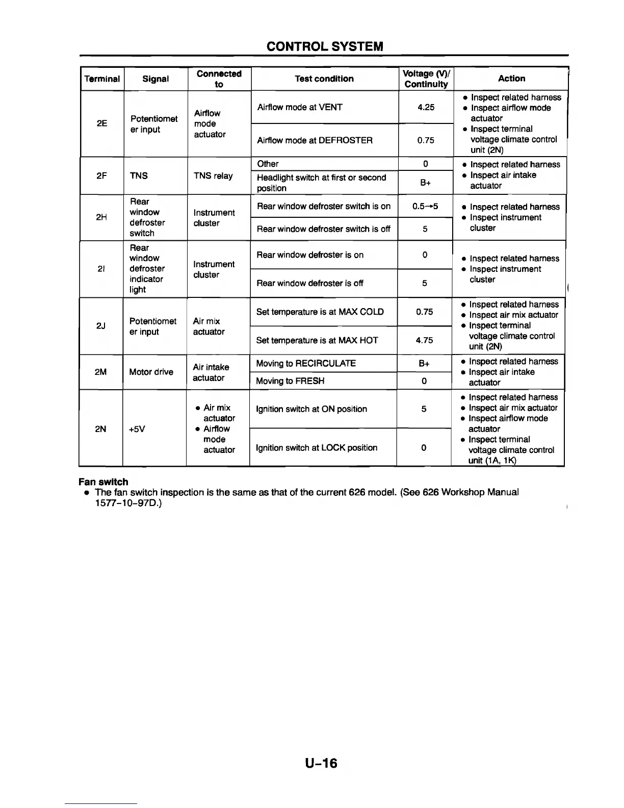
CONTROL SYSTEM
Terminal
Signal
Connected
to
Test condition
Voltage (V)/
Continuity
Action
2E
Potentiomet
er input
Airflow
mode
actuator
Airflow mode at VENT
4.25
• Inspect related harness
• Inspect airflow mode
actuator
• Inspect terminal
voltage climate control
unit (2N)
Airflow mode at DEFROSTER 0.75
2F
TNS
TNS relay
Other
0
• Inspect related harness
• Inspect air intake
actuator
Headlight switch at first or second
position
B+
2H
Rear
window
defroster
switch
Instrument
cluster
Rear window defroster switch is on 0.5-*5
• Inspect related harness
• Inspect instrument
cluster
Rear window defroster switch is off 5
2I
Rear
window
defroster
indicator
light
Instrument
cluster
Rear window defroster is on 0
• Inspect related harness
• Inspect instrument
cluster
I
Rear window defroster is off 5
2J
Potentiomet
er input
Air mix
actuator
Set temperature is at MAX COLD 0.75
• Inspect related harness
• Inspect air mix actuator
• Inspect terminal
voltage climate control
unit (2N)
Set temperature is at MAX HOT
4.75
2M Motor drive
Air intake
actuator
Moving to RECIRCULATE B+
• Inspect related harness
• Inspect air intake
actuator
Moving to FRESH 0
2N +5V
• Air mix
actuator
• Airflow
mode
actuator
Ignition switch at ON position
5
• Inspect related harness
• Inspect air mix actuator
• Inspect airflow mode
actuator
• Inspect terminal
voltage climate control
unit (1A, 1K)
Ignition switch at LOCK position
0
Fan switch
• The fan switch inspection is the same as that of the current 626 model. (See 626 Workshop Manual
1577-10-97D.)
U-16


 To Next Page