ON-BOARD DIAGNOSTIC
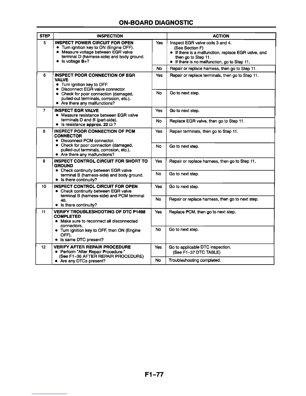
STEP
INSPECTION ACTION
5 INSPECT POWER CIRCUIT FOR OPEN
• Turn ignition key to ON (Engine OFF).
• Measure voltage between EGR valve
terminal D (harness-side) and body ground.
• Is voltage B+?
Yes Inspect EGR valve coils 3 and 4.
(See Section F)
• If there is a malfunction, replace EGR valve, and
then go to Step 11.
• If there is no malfunction, go to Step 11.
No Repair or replace harness, then go to Step 11.
6
INSPECT POOR CONNECTION OF EGR
VALVE
• Turn ignition key to OFF.
• Disconnect EGR valve connector.
• Check for poor connection (damaged,
pulled-out terminals, corrosion, etc.).
• Are there any malfunctions?
Yes Repair or replace terminals, then go to Step 11.
No Go to next step.
7
INSPECT EGR VALVE
• Measure resistance between EGR valve
terminals D and B (part-side).
• Is resistance approx. 22 i2 ?
Yes Go to next step.
No Replace EGR valve, then go to Step 11.
8 INSPECT POOR CONNECTION OF PCM
CONNECTOR
• Disconnect PCM connector.
• Check for poor connection (damaged,
pulled-out terminals, corrosion, etc.).
• Are there any malfunctions?
Yes
Repair terminals, then go to Step 11.
No Go to next step.
9 INSPECT CONTROL CIRCUIT FOR SHORT TO
GROUND
• Check continuity between EGR valve
terminal B (harness-side) and body ground.
• Is there continuity?
Yes Repair or replace harness, then go to Step 11.
No
Go to next step.
10
INSPECT CONTROL CIRCUIT FOR OPEN
• Check continuity between EGR valve
terminal B (harness-side) and PCM terminal
46.
• Is there continuity?
Yes Go to next step.
No
Repair or replace harness, then go to next step.
11
VERIFY TROUBLESHOOTING OF DTC P1498
COMPLETED
• Make sure to reconnect all disconnected
connectors.
• Turn ignition key to OFF, then ON (Engine
OFF).
• Is same DTC present?
Yes Replace PCM, then go to next step.
No Go to next step.
12 VERIFY AFTER REPAIR PROCEDURE
• Perform “After Repair Procedure.”
(See F1 36 AFTER REPAIR PROCEDURE)
• Are any DTCs present?
Yes
Go to applicable DTC inspection.
(See F1-37 DTC TABLE)
No Troubleshooting completed.
F1-77
 Loading...


