Chapter 1 Before Using This Product
22
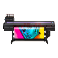
1.1 Part Names and Functions
Front
No. Name Summary
1 Platen Print area. "Platen"(P. 25)
2 Pinch rollers
Grid rollers
The pinch rollers and grid rollers are used to grip and feed the media.
"Pinch Rollers and Grid Rollers"(P. 26)
3 Capping station Includes caps, wipers, and an NCU for monitoring print head nozzle
conditions. "Capping Station"(P. 25)
4 Carriage Consists of a print head, a UV-LED lamp, and the jam sensor.
"Carriage"(P. 25)
5 Operating panel Includes operating keys and displays indicating various settings and other
items. "Operating Panel"(P. 29)
6 Clamp lever (front) Lowering the clamp lever secures the media. Raising the clamp lever
releases the media.
7 Waste ink tank Container for waste ink. "Waste Ink Tank Replacement"(P. 155)
8 Take-up unit Automatically rolls up the roll media after printing. "Take-up Unit"(P. 27)
9 Maintenance covers Open the cover to perform maintenance. Printing and automatic
maintenance are not possible while the covers are open.
10 Cutter unit Includes a media cutter cutting the media along the platen cutting slot. The
cutter unit is located at the maintenance position on the left side during
standby. "Installing Cutting Tools"(P. 82)
11 Ink IC chip slot The ink IC chip provided with the Ink bottle is inserted here. This manages
information on the Ink bottle. "Insert Ink IC Chip"(P. 43)
12 Ink status lamp This lamp indicates ink status. "Ink status lamp"(P. 26)

 Loading...


