EasyManuals Logo

Mindray BeneVision TM80 Service Manual

Mindray BeneVision TM80
210 pages
To Next Page IconTo Next Page
To Previous Page IconTo Previous Page
Page #170 background imageLoading...
Page #170 background image
8-4 TM80 Telemetry Monitor Service Manual
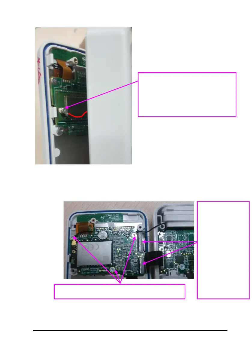
4. Remove the three M1.6x2.4 cap head screws on the main control board, open
the card fasteners of the FPC socket, and remove the two FPCs.
Three M1.6×2.4 cross recessed cheese head screws
Open
card
fasteners
of the
two FPCs
and
remove
the two
FPCs
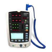
Assemble the wifi antenna connector,
the wire direction should be inside, as
shown in red.

Table of Contents

Other manuals for Mindray BeneVision TM80

Questions and Answers:

Question and Answer IconNeed help?

Do you have a question about the Mindray BeneVision TM80 and is the answer not in the manual?

Mindray BeneVision TM80 Specifications

General IconGeneral
BrandMindray
ModelBeneVision TM80
CategoryMonitor
LanguageEnglish

Related product manuals