M Series AC Servo
User Manual
43
Rev. 1.0
7/31/2019
400-820-9661
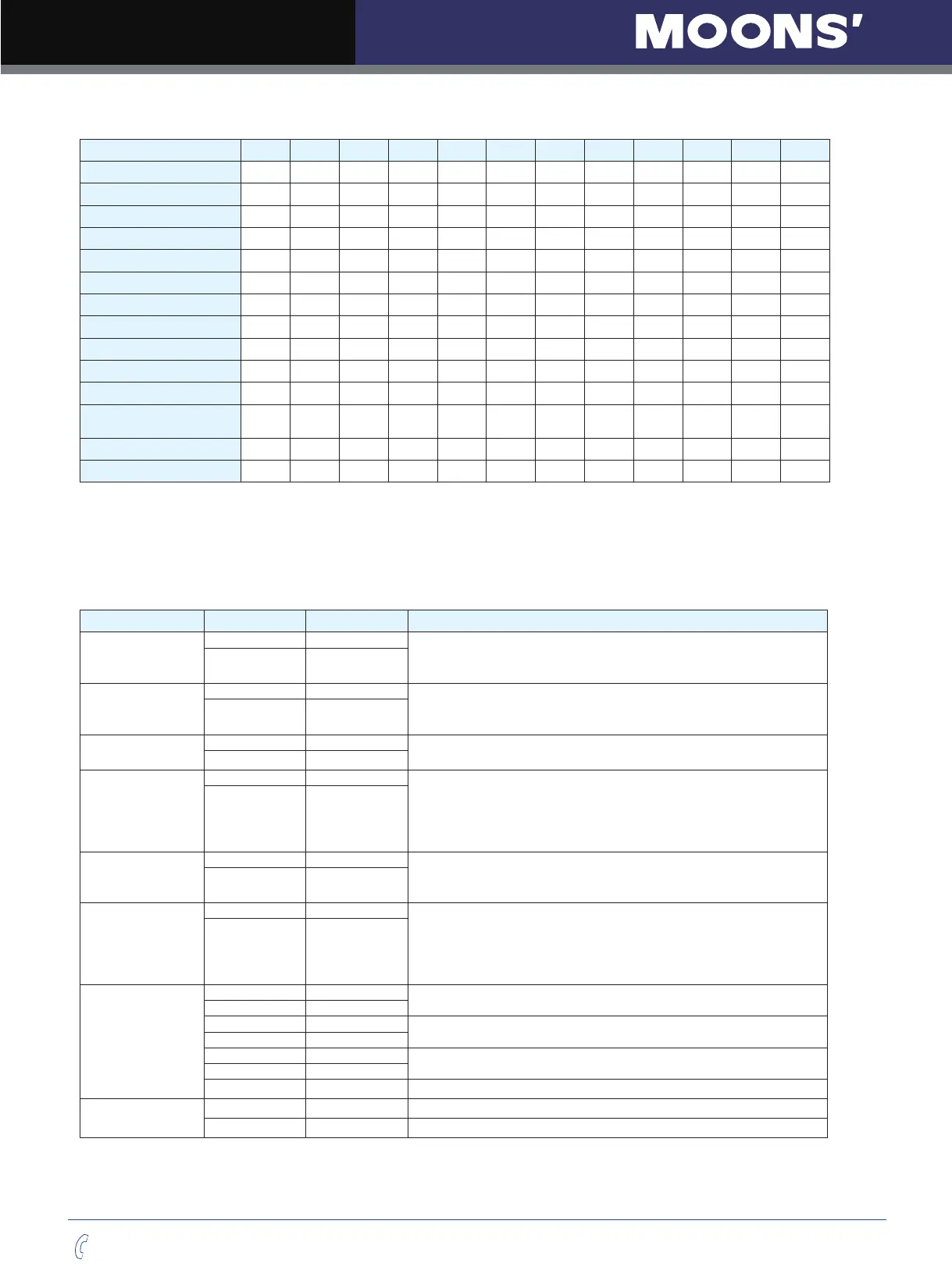
4.8.2.3 Inputs Function List
1 2 3 4 5 6 7 8 9 10 11 12
Step
■
DIR
■
CW Limit
●
CCW Limit
●
Start/Stop
▲▼
Direction
▲▼
Servo enable
●
Alarm clear
●
Speed selection 1,2,3
▲ ▲ ▲
Global gain selection
■
Control mode selection
●
Pulse encoder
Resolution selection
■
Pulse Inhabit
■
General Input
● ● ● ● ● ● ● ● ● ● ● ●
■– Position Mode ▲– Velocity Mode ▼ – Torque Mode ● – All Modes
4.8.2.4 Output Signals
M2 series AC servo drive has 6 programmable digital output signals available; each of the output can be
specified with different function via parameter settings.
Signal Symbol Pin NO. Details
Y1
Y1+ 37
This output has two functions:
●
Alarm Output.
●
General purpose output.
Y1- 36
Y2
Y2+ 11
This output has two functions:
●
Motor brake control output.
●
General purpose output.
Y2- 10
Y3
Y3+ 42
●
Torque Reached Output.
●
General purpose output.
Y3- 33
Y4
Y4+ 43
●
Moving signal output, output signal when dynamic position error less
than set value in position mode.
●
Velocity reach output. Output signal when actual speed is same as the
target speed and the speed ripple less than ripple range.
●
General purpose output.
Y4- 33
Y5
Y5+ 40
●
Servo ready output. Output servo ready signal when the drive is ready
to be controlled and without alarm.
●
General purpose output.
Y5- 41
Y6
Y6+ 14
●
In position signal output, output signal when in position, and the
position error less than set value in position mode.
●
Tach out output. Tach output, produces pulses relative to the motor
position with configurable resolution.
●
General purpose output.
Y6- 13
Encoder pulse
feedback Output
AOUT+ 21
The encoder feedback phase A line drive output.
AOUT- 22
BOUT+ 48
The encoder feedback phase B line drive output.
BOUT- 49
ZOUT+ 23
The encoder feedback phase Z line drive output.
ZOUT- 24
ZOUT 19
The encoder feedback phase Z output. (Open collector)
+10V
Output
+10V User 20
+10VDC user, max 100mA
USER_GND 25
+10VDC user Ground