M Series AC Servo
User Manual
70
Rev. 1.0
7/31/2019
400-820-9661
6. Preoperational mode
When preoperational mode is operating, please disconnect servo motor from any mechanical system to
prevent any damages and accidents. Please perform this operation under no load condition.
6.1 Inspection Before Trail Run
In order to avoid any accidents and damages to servo drive and mechanical systems, we strongly
recommend following safety checks before you turn on the drive.
1) Connection inspections
Please ensure secure wirings for power connector P1, motor connector P2, Encoder connector CN3,
communication connector CN1. Ensure wirings connection, and wires are correctly insulated (not short
circuit) for all connectors.
Ensure ground wire from power connector P1, and motor connector P2 are securely connected
(screwing) to the shield ground.
2) Power supply inspection
Check and ensure voltage supplies between L1/L2/L3, meets drive
’
s power supply specifications.
Check and ensure voltage between L1C/L2C is within the correct supply voltage range.
3) Ensure secure installation of servo drive and motor.
4) Ensure no load is installed on the servo motor.
6.2 Trail Run Procedure
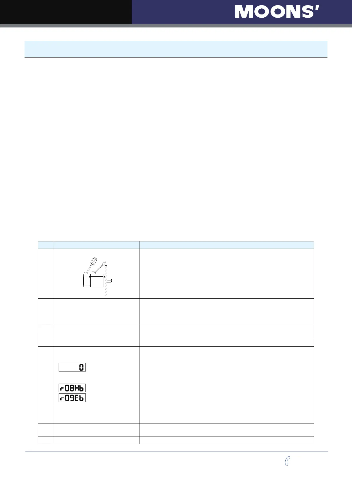
Step Details Description
1
Please securely install the motor.
1) The motor can be installed on the machine.
2) Ensure no load is installed on the servo motor.
2
Please ensure the wiring between the
drive and motor is correctly.
1.Terminal U,V,W and FG must connect to Red, Yellow ,Blue and Yellow/Green
cable separately (U:Red, V:Yellow, U:Blue, FG:Yellow/Green).If not connect to the
specified cable and terminals, then the drive cannot control motor.
2.Ensure to connect encoder cable to CN2 connector correctly.
3
Please make sure the main power
circuit wiring connect correctly.
Refer to Section 3.1 Connecting to Peripheral Devices to confirm the main power
circuit wiring connect correctly.
4
Supply the Power
Do
not supply 380VAC power supply into the servo system.
5
The LED Display will show as follows
without alarm:
When the alarm occurs, it will display:
1. When the power is on ,the normal display should be shown without any alarm
codes and the drive is disabled.
2. If display shows alarm codes such as r-08 and r-09. It means that the encoder
feedback connection is incorrectly. Check if the encoder wiring of servo motor is
loose or incorrect.
3. Please refer to the other alarm trouble shooting10.
6
User need to setup a motor
brake control circuit when using a
electromagnetic brake motor.
Please refer to Section 3.4 Electromagnetic Brake for more details.
7 Motor Configuration
Configure the correct motor that has been used with the M2 Servo Suit or the
operation panel. Please refer to Motor Configuration 6.3
8 JOG Trail Run without Load Ready to run JOG trail if all steps above are done.