M Series AC Servo
User Manual
41
Rev. 1.0
7/31/2019
400-820-9661
4.8.2 Signals Description of Connector CN2
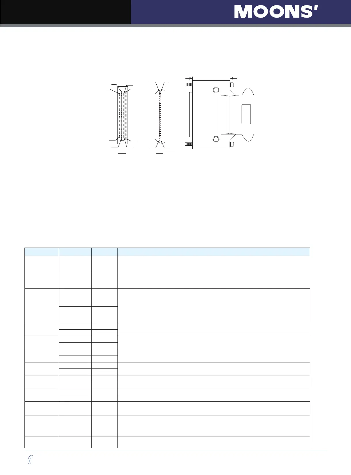
4.8.2.1 The Layout of CN2 Connector
A
B
A视图
25
50
26
1
27
26
1
2
24
25
50
49
B视图
4.8.2.2 Input Signals
M2 series AC servo drive has 12 programmable digital inputs as well as 2 analog inputs.
Each of the input can be specified with different function via parameter settings. The functions are as
follows:
• Specified function signals: i.e. STEP/DIR signal, motor enable/disable signals.
• General purpose signal: In velocity mode, torque mode, Q program mode, or SCL mode, it is used as
general purpose signal with no specified functions.
Signal Symbol Pin NO. Details
X1
X1+ 3
This input has three functions:
●
Accept STEP pulse input such as STEP signals, CW pulse, A pulse in
Position mode.
●
Run/Stop input in torque or velocity mode.
●
General purpose input.
X1- 4
X2
X2+ 5
This input has three functions:
●
Accept STEP pulse input such as Direction signals, CCW pulse,
B pulse in position mode.
●
Direction input in torque or velocity mode.
●
General purpose input.
X2- 6
X3
X3+ 29
●
Enable/Disable input.
●
General purpose input.
X3- 31
X4
X4+ 35
●
Alarm Reset Input, used to reset drive alarm.
●
General purpose input.
X4- 34
X5
X5+ 8
●
Limit Sensor Input.
●
General purpose input.
X5- 2
X6
X6+ 9
●
Limit Sensor Input.
●
General purpose input.
X6- 1
X7
X7+ 39
●
Gain Select Input in all control mode.
●
General purpose input.
X7- 38
X8
X8+ 12
●
Switch Control mode between main mode and second mode.
●
General purpose input.
X8- 32
X9 X9 26
●
Dividing Switch, change the pulses per revolution for electronic Gearing.
●
General purpose input.
X10 X10 27
●
Pulse Inhibited Input. Ignore the pulse input when this input is activated
in position mode.
●
Speed Selecting Input 1 in change Speed mode.
●
General purpose input.
X11 X11 28
●
Speed Selecting Input 2 in change Speed mode.
●
General purpose input.