M Series AC Servo
User Manual
31
Rev. 1.0
7/31/2019
400-820-9661
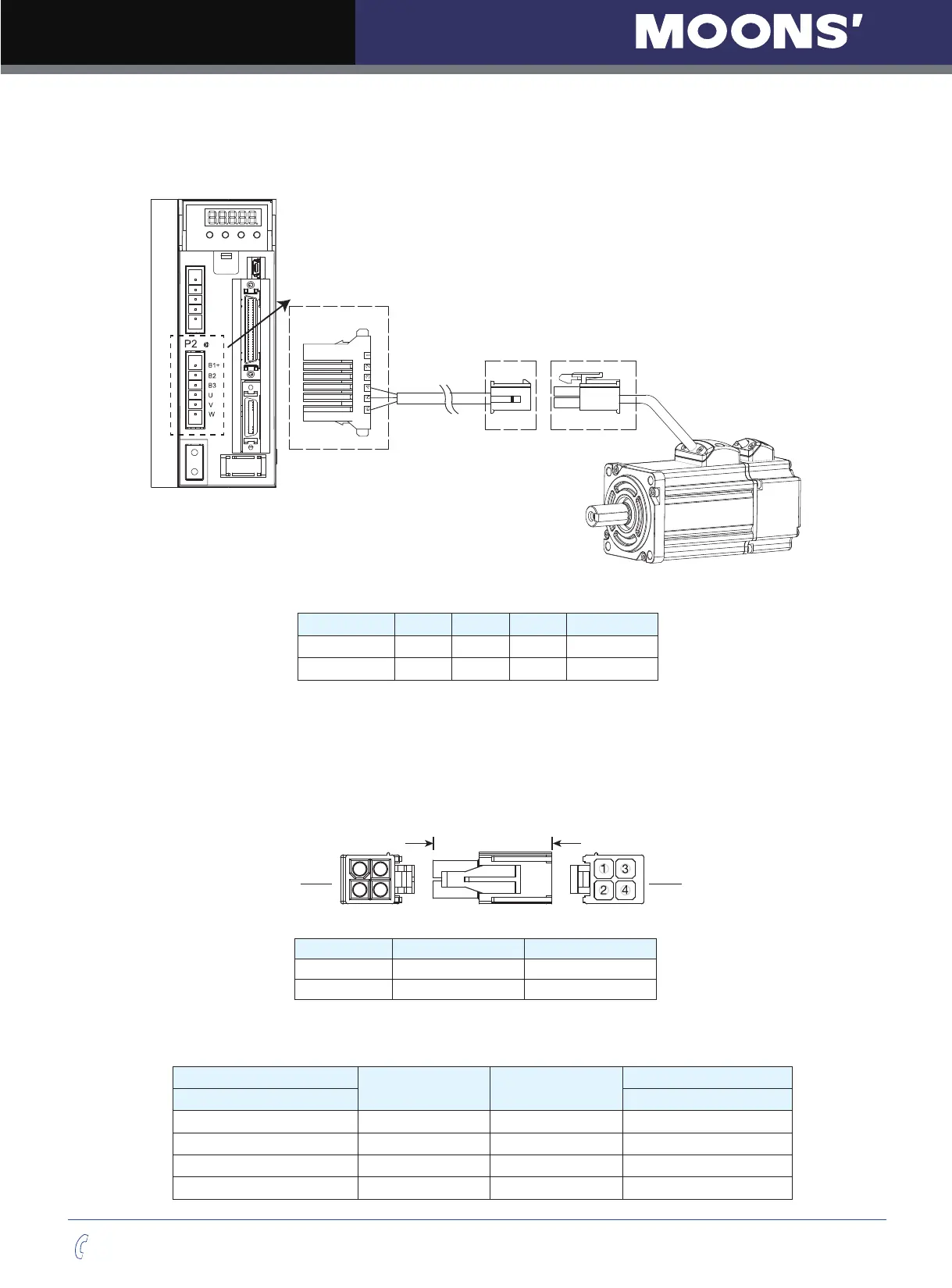
4.2 Wiring to the Connector, P2
4.2.1 Motor Power Cable Conguration
P2 interface of the drive
Connector of Motor Power
extension cable
Connector of
the motor lead wire
PIN 1 2 3 4
Signal U V W PE
Colour Red Yellow Blue Yellow/Green
NOTE: Please refer to section 4.2.2 Motor Power Cable Connector Specifications for details
4.2.2 Motor Power Cable Connector Specifications
◆
PIN Assignment
A B
Vew A Vew B
Type Motor Side(Plug) Plug-in(Housing)
Housing AMP 172167-1 AMP 172159-1
Terminal AMP 170360-1 AMP 170362-1
◆
Model of Motor Connector
Drive Side(P2)
Signal Colour
Motor Side(Housing)
(JST) S06B-F32SK-GGXR AMP 172159-1
4 U Red 1
5 V Yellow 2
6 W Blue 3
Grounding Screw PE Yellow/Green 4