M Series AC Servo
User Manual
10
Rev. 1.0
7/31/2019
400-820-9661
2. Product Description
2.1 Unpacking Check
Please refer to this section to confirm the model of servo drive and servo motor .
A complete and workable AC servo system should include the following parts:
1. Matched Servo drive and Servo motor
2. A power cable connect the drive to the servo motor(Optional)
3. An feedback encoder cable connect the drive to the motor (Optional)
4. A mini USB cable connect the port CN1 to PC for communication.(Optional)
5. 50-PIN connector (For I/O connections, Port CN2) (Optional)
6. 26-PIN connector(For encoder feedback, Port CN3 ) (Optional)
7. 6-PIN connector(IEEE1394, Port CN4, Port CN5)(Optional)
8. RJ-45 connectors (For RS-485 or CANopen communication, Port CN6 and CN7)(Optional)
9. 5-PIN connector (For L1,L2,L3,L1C,L2C)
10. 6-PIN connector(For U,V,W,B1+,B2,B3)
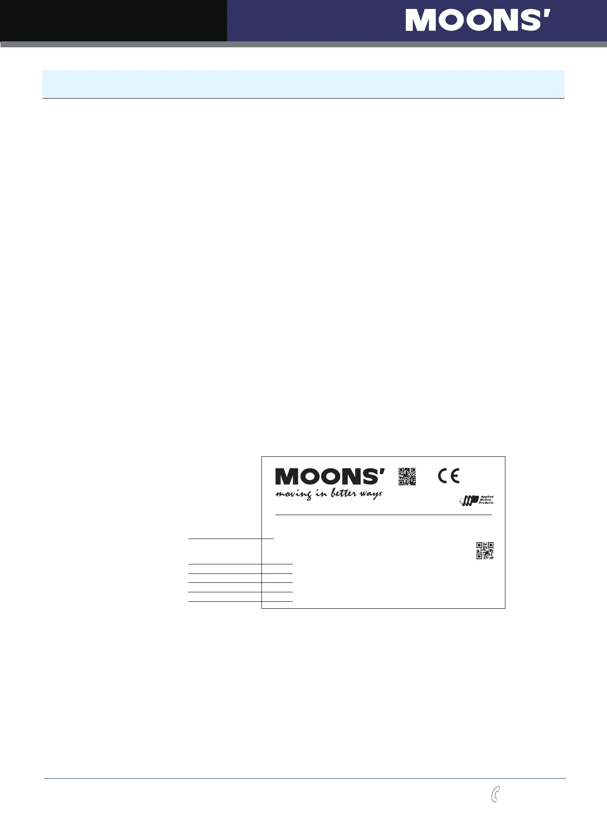
2.2 Servo Drive Model Introduction
2.2.1 Drive Name Plate Description
Model No.
Input/Output Voltage
Phase
Rated Current
Frequency
Rated Power
Model No. XXXX-XXXXX
Serial No.
09450001
INPUT
1.8 A
OUTPUT
VOLT.
1 /3φ φ
0-240VAC
3φ
2.6 A/1.5A
200-240VAC
PHASE
F.L.C
FREQ.
POWER
50/60Hz
0-400Hz
200W
AC SERVO
DRIVE
M2
Assembled in China
RoHS
Designed in California by