M Series AC Servo
User Manual
83
Rev. 1.0
7/31/2019
400-820-9661
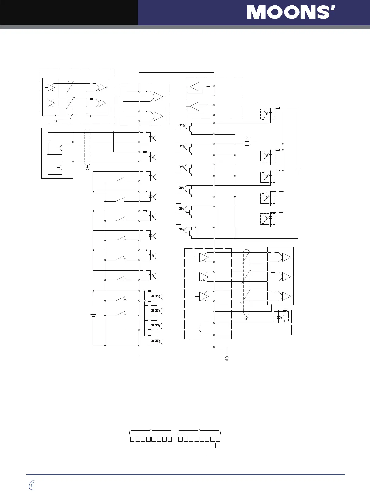
7.2.1 Digital Pulse Position Mode Connection Diagram
3
X1+
4
X1-
5
X2+
6
X2-
29
X3+
31
X3-
35
X4+
34
X4-
8
X5+
2
X5-
9
X6+
1
X6-
39
X7+
38
X7-
12
X8+
32
X8-
7
COM
26
X9
27
X10
28
X11
30
X12
1.5K
1.5K
1.5K
1.5K
1.5K
1.5K
1.5K
1.5K
AOUT+
AOUT-
BOUT+
BOUT-
ZOUT+
ZOUT-
21
22
48
49
23
24
CZ
DGND
19
15
High Speed Pulse Input
44
PULSH1
45
PULSH2
46
SIGNH1
47
SIGNH2
37
Y1+
36
Y1-
11
Y2+
10
Y2-
40
Y5+
41
Y5-
14
Y6+
13
Y6-
42
Y3
43
Y4
OUT-
+
-
+
-
16
15
18
17
DGND
DGND
ANA1
ANA2
Enable Signal Input
Alarm Reset
Limit Sensor
Limit Sensor
Gain Select
Control mode Switch
Analog Input
Speed Command
Torque Command
Open Collector Output
High Speed Differential Input
44
PULSH1
45
PULSH2
46
SIGNH1
47
SIGNH2
Controller
DGND
FG
Differential Pulse Signal
VDC
VDC Spec.
5-24VDC
Alarm Output
Brake Control Output
Servo Ready
In Position
5-24VDC
Drive
A+
A-
B+
B-
Z+
Z-
DGND
5-24VDC
Encoder Phase A Output
Encoder Phase B Output
Encoder Phase Z Output
Phase Z (Open Collector Output)
DGND
15
VDC
33
Pulse Inhibited Input.
DGND
25
FG
50
Dividing Switch
Torque Reached Output
Velocity Reached Output
Encoder
Feedback
Output
7.2.2 Input Pulse Type And Input Noise Filter
There are three types of pulse modes: STEP & Direction; CW/CCW Pulse; A/B Quadrature.
Parameter P-43 (SZ) uses decimal numbers to define pulse input type, polarity and input filter frequency.
Transfer into binary number, the HIGHER 8 bits of the number defines input filter frequency, and the
LOWER 8 bit defines pulse input type, and polarity.
Input Noise Filter
Higher 8 Bits
Lower 8 Bits
Pulse Polarity
Pulse Type