M Series AC Servo
User Manual
32
Rev. 1.0
7/31/2019
400-820-9661
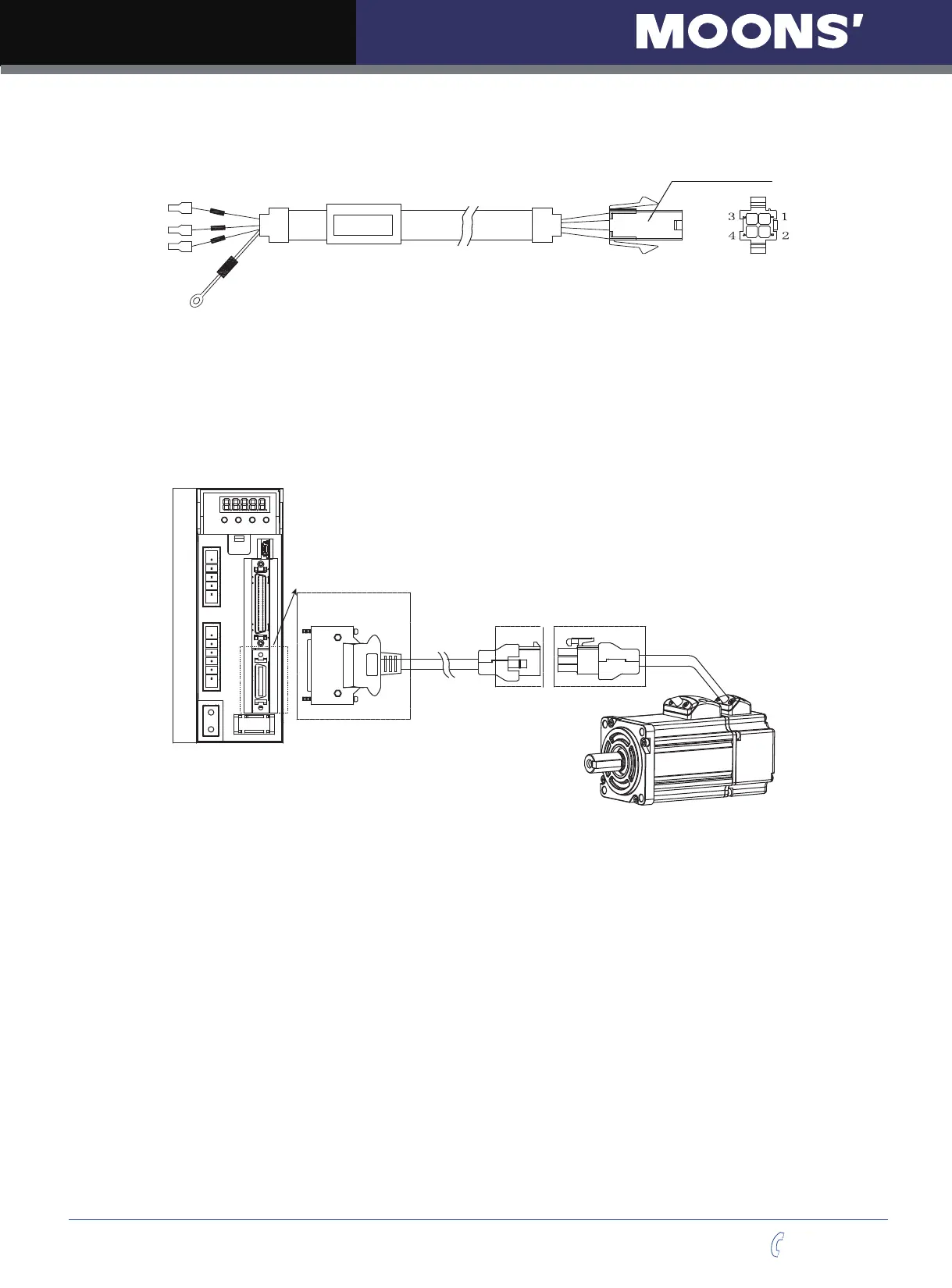
4.2.3 Wiring Diagram Of Motor Extend Cable
Housing: 172159-1(AMP)
Terminal: 170362-1(AMP)
NOTE: Ensure U/V/W is following the order of RED/YELLOW/BULE. Wrong connections will cause
motor stop rotation, or wrong rotary directions.
4.3 Encoder Connector CN3
4.3.1 Motor Encoder Feedback Cable Configuration
P2
C
N
3
B1+
B2
B3
U
V
W
CN3 interface of the drive
Connector of Encoder
extension cable
Connector of
the encoder lead wire
NOTE: Please refer to section 4.1.5.2 Motor Power Cable Connector Specifications for details