MOTOROLA M68020 USER’S MANUAL 10-3
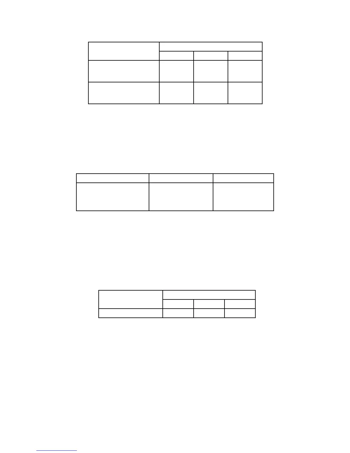
Table 10-1. θ
JA
vs. Airflow—MC68020 CQFP Package
Airflow in Linear Feet/Minute
θ
JA
0* 200 500
Maximum
No Heatsink
With Heatsink
46
35
28
20
24
18
Typical
No Heatsink
With Heatsink
43
32
25
17
21
15
*Natural convection
Table 10-2 shows the relationship between clock speed and power dissipation for any
package type.
The worst case operating conditions are used for thermal management
design, while typical values are used for reliability analysis.
Table 10-2. Power vs. Rated Frequency
(at T
J
Maximum = 110°C)
Rated Frequency (MHz) P
D
Maximum (Watts) P
D
Typical (Watts)
33
25
20
16
1.4
1.2
1.0
0.9
0.84
0.72
0.60
0.54
Table 10-3 shows the relationship between board temperature rise and power dissipation
in the test environment for the CQFP package.
Derate θ
JA
based on measurements made
in the application by adding (0.8/P
D
)
*
[T
ba(application)
– T
ba(table)
] to the θ
JA
values in the
table.
Board temperature was measured on the top surface of the board directly under the
device.
Table 10-3. Temperature Rise of Board vs. P
D
—MC68020 CQFP Package
P
D
Natural Convection 0.6W 1.0W 1.75W
T
ba
(°C)—No Heatsink 18 27 53
Values for thermal resistance presented in this document were derived using the
procedure described in Motorola Reliability Report 7843, “Thermal Resistance
Measurement Method for MC68XX Microcomponent Devices,” and are provided for
design purposes only. Thermal measurements are complex and dependent on procedure
and setup. User-derived values for thermal resistance may differ.

 Loading...
