5 Mounting
Maschinenfabrik Reinhausen 201434 3550953/00 ENTAPCON® 230 pro
The screws for fixing to the wall are not included in the scope of supply. The
screw length required depends on the wall thickness.
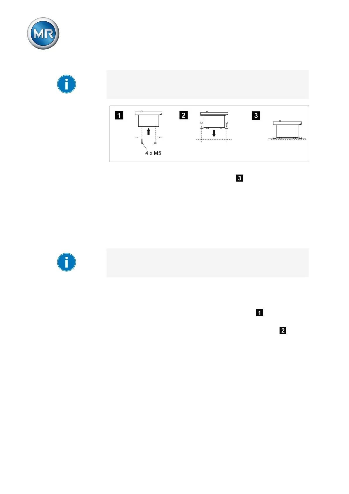
Figure 19: Wall mounting with mounting brackets
ð The device is mounted and can be wired up .
Proceed with wiring as shown in the connection diagram and as described in
the Connecting device [► 37] section.
Cap rail mounting
Alternatively, the device can be fitted with a cap rail clip (aluminum extrusion
with central integrated wire spring). This enables you to mount the device on
a cap rail (in accordance with EN 50022).
When attaching the cap rail, sufficient space for the device must be planned
for. At least 5 cm (1.97 in) of space must be provided above and at least
35 cm (13.78 in) below the fixing bolts of the cap rail for the device housing.
To mount the device using the cap rail, proceed as follows:
1. Lay the device carefully on the door.
2. Screw the cap rail clip into the two top holes on the rear with the M5
hexagon socket countersunk head screws provided .
3. Suspend the cap rail clip in the cap rail and push the underside carefully
towards the wall until the clip can be heard to click into place .
5.2.3