5 Mounting
Maschinenfabrik Reinhausen 201438 3550953/00 ENTAPCON® 230 pro
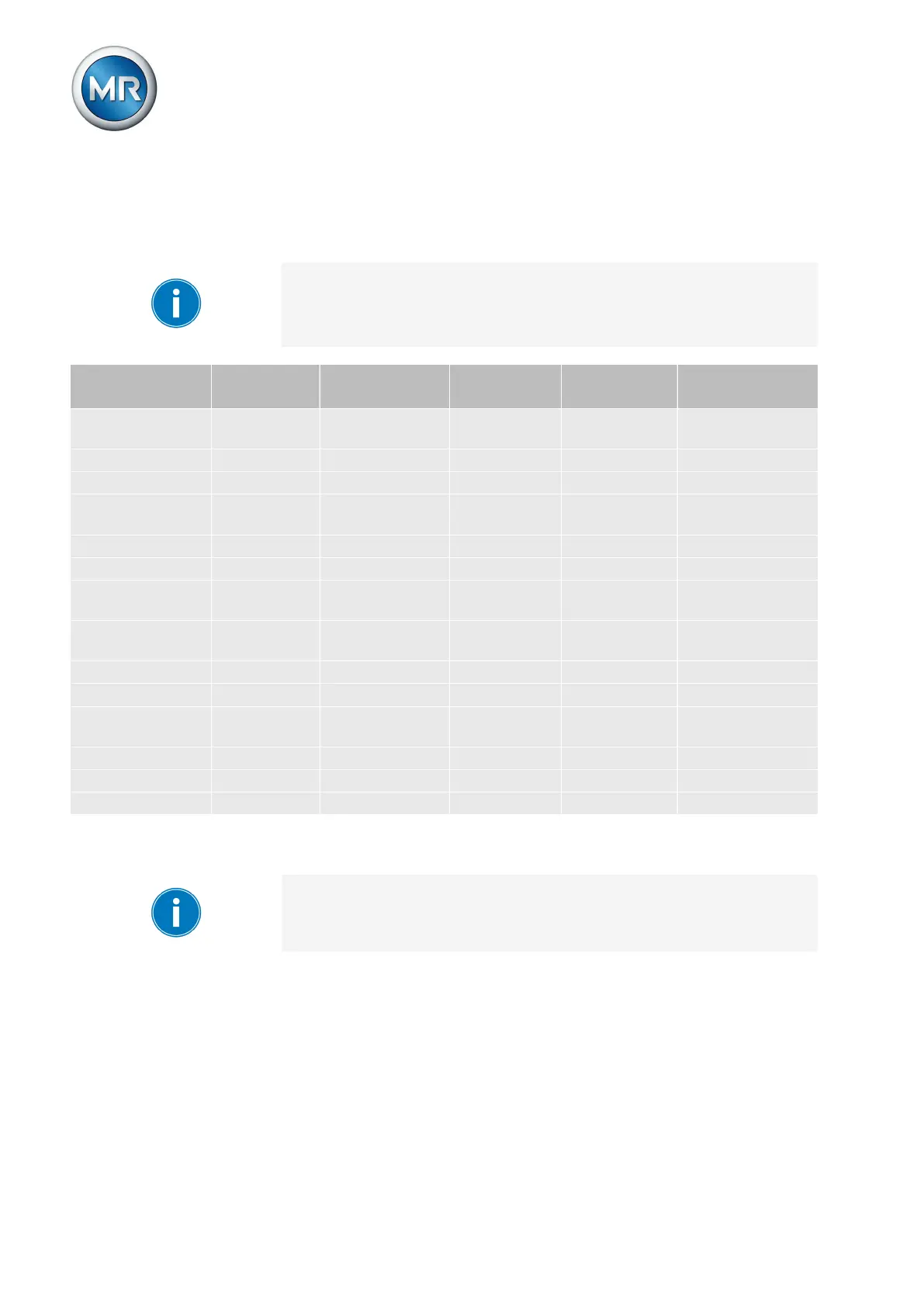
Cable recommendation
Please note the following recommendation from Maschinenfabrik Reinhau-
sen when wiring the device.
Excessive electrical power can prevent the relay contacts from breaking the
contact current. In control circuits operated with alternating current, take into
account the effect of the line capacitance of long control lines on the func-
tion of the relay contacts.
Cable Terminal Cable type Wire cross-
section
Max. length Max. permissi-
ble torque
Analog input X7 shielded
(< 25 Ω/km)
1.5 mm² 400 m -
Signal inputs X4 Shielded 1.5 mm² - 0.6 Nm
RS232 SUB-D - Shielded 0.25 mm² 25 m -
RS485 - shielded
(< 50 Ω/km)
0.75 mm² 1000 m -
Ethernet RJ45 - min. CAT5 - - -
Relay outputs* X3 Unshielded 1.5 mm² - 0.6 Nm
Relay outputs*
optional
X4 Unshielded 1.5 mm² - 0.6 Nm
Current measure-
ment
X1:5/6/9 Unshielded 4 mm² - 1.5 Nm
Relay outputs X5 Unshielded 1.5 mm² - 0.6 Nm
Signal inputs X6 Unshielded 1.5 mm² - 0.6 Nm
Digital tap posi-
tion inputs
X6 Shielded 1.5 mm² - 0.6 Nm
Auxiliary voltage X6 Unshielded 1.5 mm² - 0.6 Nm
Power supply X2:3/4 Unshielded 1.5 mm² - 0.6 Nm
CAN bus - Shielded 1.0 mm² 2000 m -
Table 7: Cable recommendation for connection cable
*) Note the line capacitance, see note above.
Cable clips X1 to X4 are on the MIO card of the device. Cable clips X5 to X7
are on the PIO card of the device.
Information about laying fiber-optic cable
To ensure the smooth transfer of data via the fiber-optic cable, you must en-
sure that mechanical loads are avoided when laying the fiber-optic cable and
later on during operation.
5.3.1
5.3.2