7 Functions and settings
Maschinenfabrik Reinhausen 201466 3550953/00 ENTAPCON® 230 pro
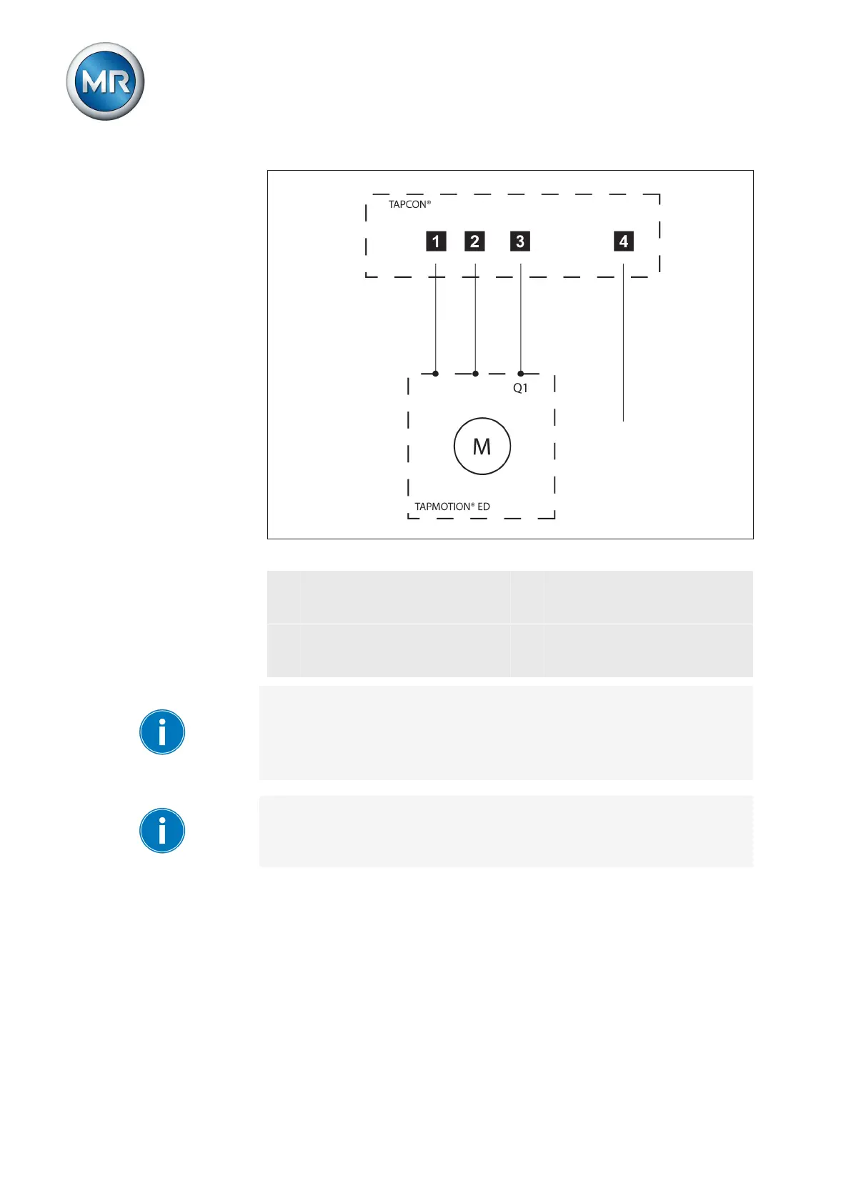
Figure 38: Wiring for motor runtime monitoring
1 Motor running control input
I/O
3 Motor protective switch trip-
ped GPO output relay (option-
al)
2 Motor protective switch trig-
gered control input I/O (op-
tional)
4 Motor runtime exceeded GPO
output relay (optional)
If you want to use the output relay, the feedback from the motor-drive unit
Motor protective switch triggered must be wired to a control input and para-
meterized. This message resets the Motor runtime exceeded output relay
when the motor protective switch is switched back on and activates the Mo-
tor protective switch triggered message.
If the runtime monitoring is set to "0.0 s", this equates to it being switched
off.
To set the motor runtime, proceed as follows: