7 Functions and settings
Maschinenfabrik Reinhausen 2014 713550953/00 EN TAPCON® 230 pro
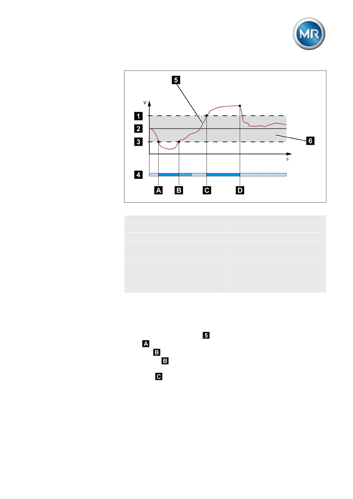
Figure 39: Response of the regulation function with delay time T1
1 + B %: Upper limit 4 Set delay time T1
2 V
desired
: Desired value 5 V
actual
: Measured voltage
3 - B %: Lower limit 6 B%: Tolerance bandwidth
A V
actual
is outside the band-
width. Delay time T1 starts.
B V
actual
is within the bandwidth
before delay time T1 is com-
plete.
C V
actual
is outside the band-
width. Delay time T1 starts.
D V
actual
is still outside the band-
width when delay time T1 is
complete. Tap-change opera-
tion is initiated.
Response with delay times T1 and T2
Delay time T2 can be used to correct major control deviations more quickly.
Ensure that you set a lower value for delay time T2 than delay time T1.
If the measured voltage V
actual
deviates from the set bandwidth for a long
period , a control impulse is output to the motor-drive unit after the set de-
lay time T1 . If the measured voltage V
actual
is still outside the bandwidth,
delay time T2
starts once delay time T1 is complete. Once delay time T2
is complete, a control impulse is again output to the motor-drive unit for the
tap change to return to the tolerance bandwidth.