7 Functions and settings
Maschinenfabrik Reinhausen 2014 953550953/00 EN TAPCON® 230 pro
Setting Measurement meth-
od
Phase difference
-30 3PH 3 phase -30°
Table 18: Set values for transformer circuit
Note the following sample circuits to select the correct transformer circuit.
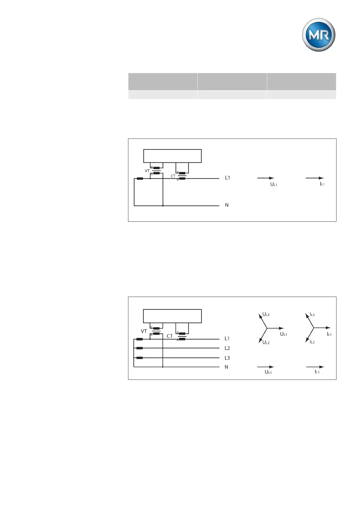
Circuit A: 1-phase measurement in 1-phase grid
Figure 54: Phase difference 0 1PH
▪ The voltage transformer VT is connected to the outer conductor and
neutral conductor.
▪ The current transformer CT is looped into the outer conductor.
▪ The voltage V
L1
and current I
L1
are in phase.
▪ The voltage drop on an outer conductor is determined by the current I
L1
.
Circuit B: 1-phase measurement in 3-phase grid
Figure 55: Phase difference 0 3PHN
▪ The voltage transformer VT is connected to the outer conductors L1 and
the neutral conductor.
▪ The current transformer CT is looped into the outer conductor L1.
▪ The voltage V and current I are in phase.
▪ The voltage drop on an outer conductor is determined by the current I
L1
.