7 Functions and settings
Maschinenfabrik Reinhausen 2014 973550953/00 EN TAPCON® 230 pro
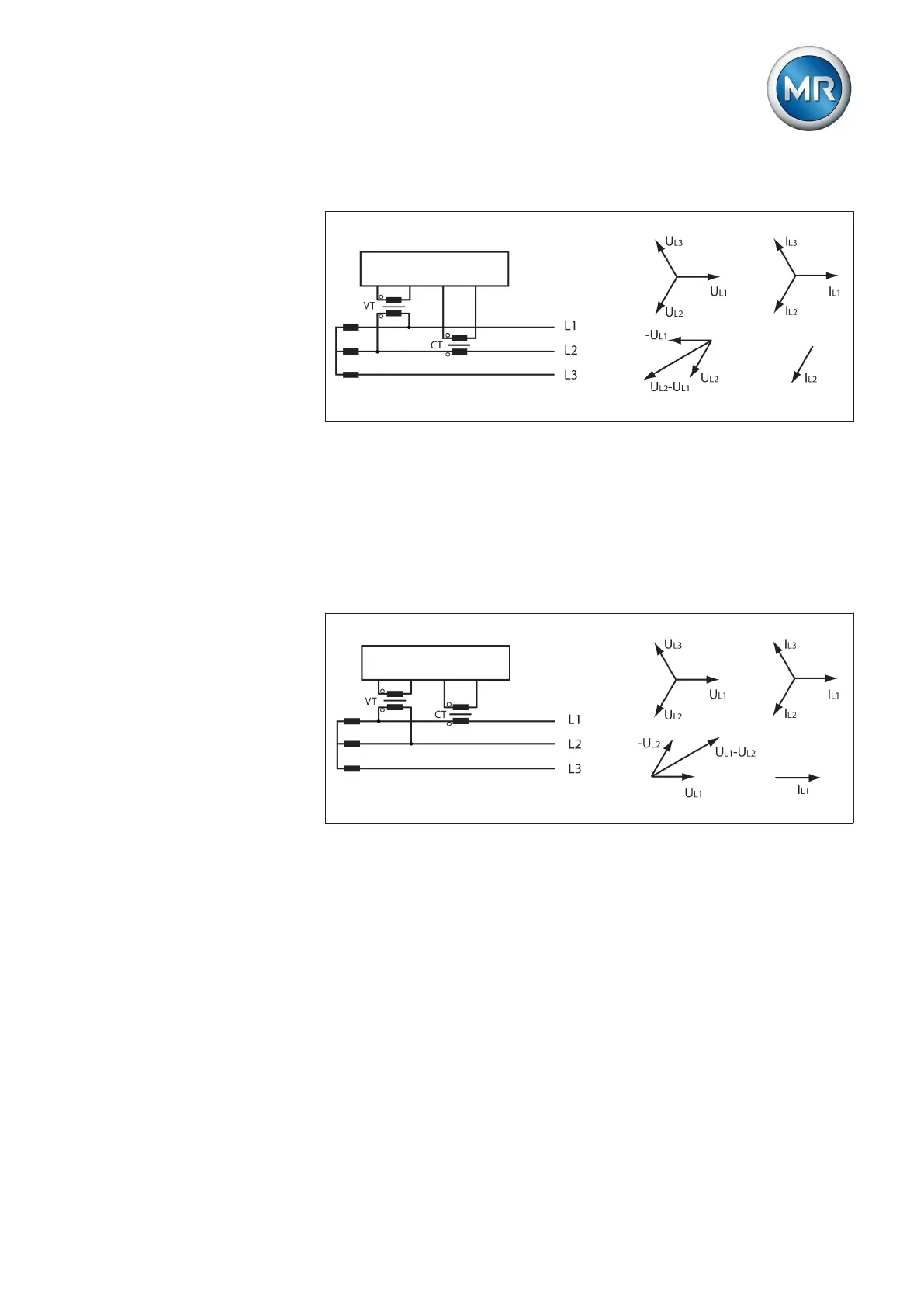
Circuit E
Figure 58: Phase difference 30 3PH
▪ The voltage transformer VT is connected to the outer conductors L1 and
L2.
▪ The current transformer CT is looped into the outer conductor L2.
▪ The current I
L2
is ahead of voltage V
L2
-V
L1
by 30°.
▪ The voltage drop on an outer conductor is determined by the current I
L2
.
Circuit F
Figure 59: Phase difference -30 3PH
▪ The voltage transformer VT is connected to the outer conductors L1 and
L2.
▪ The current transformer CT is looped into the outer conductor L1.
▪ The current I
L1
lags behind V
L1
-V
L2
by 30°. This corresponds to a phase
shift of -30°.
▪ The voltage drop on an outer conductor is determined by the current I
L1
.
To set the phase difference for the transformer circuit, proceed as follows: