Appendix
124
DIP Switch Settings for Switching Modules
Each component in a Matrix System
®
Display is assigned a Position number which is used to activate that
component during a demonstration. Each Component Chain consists of one or more Switching Modules,
depending on the number of components to be switched in that Chain. The table below will help you make
the proper settings on each Switching Module to assign it the correct Chain designation, and those on the
next page will help you find the corresponding component Position designations. When installing a Matrix
System Switching System, be sure to write the numbers assigned to each Module, and to the Positions on
each Module, in indelible marker right on the circuit board (see Figure 34, page 63).
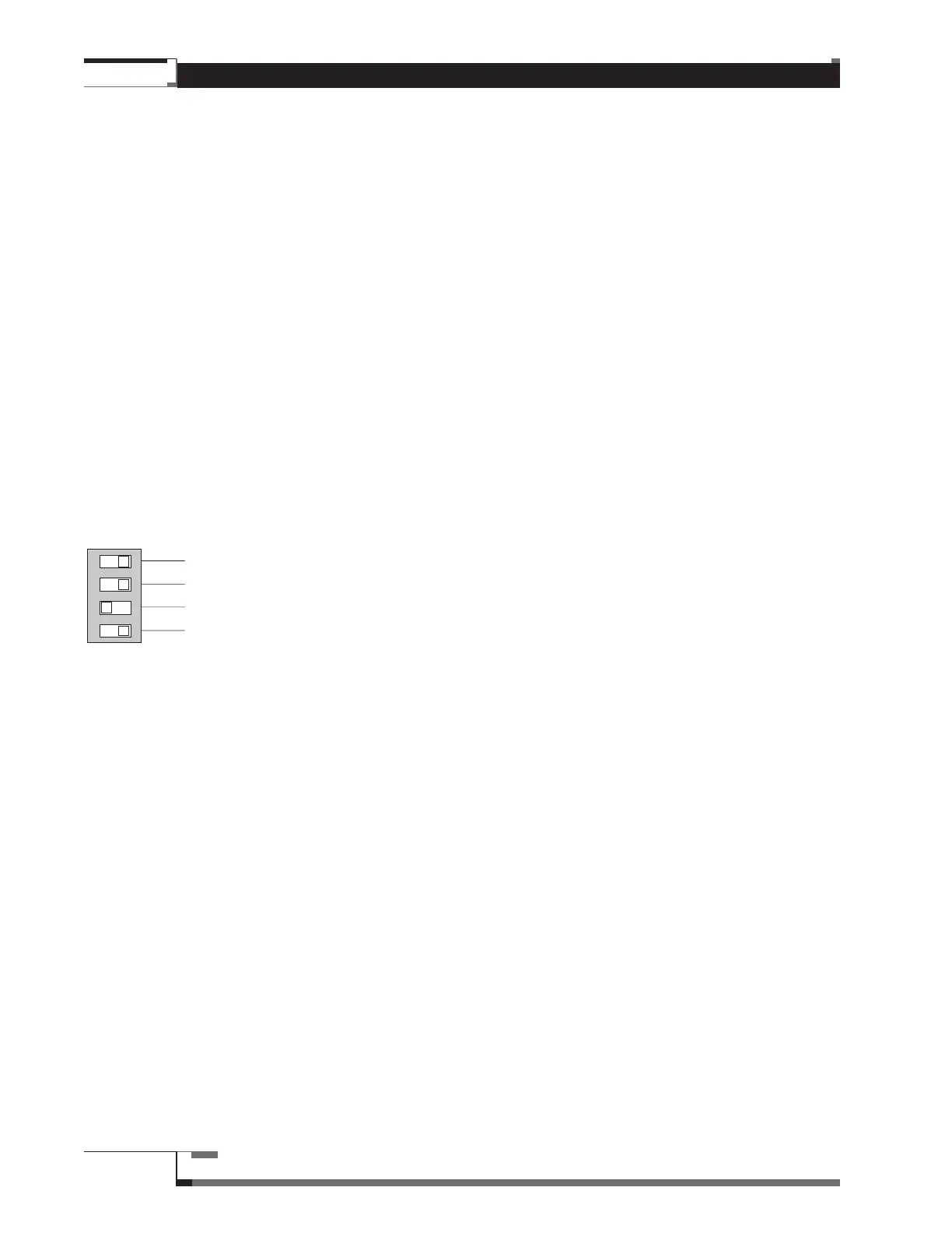
Setting Chain Designation
In Figure 59, the top row of digits represents the numbers you would assign to the Switching Modules in a
Chain; -1 being the first Module, -2 being the second and so on. The first column of digits on the left
represents the actual DIP Switches. Cross reference to find the correct DIP switch Settings for each Module
in a Chain.
DIP Switch Number (Chain Designation) Assigned to Switching Module
-1 -2 -3 -4 -5 -6 -7 -8 -9 -10 -11 -12 -13
1 ON OFF ON OFF ON OFF ON OFF ON OFF ON OFF ON
2 ON ON OFF OFF ON ON OFF OFF ON ON OFF OFF ON
3 ON ON ON ON OFF OFF OFF OFF ON ON ON ON OFF
4 ON ON ON ON ON ON ON ON OFF OFF OFF OFF OFF
Figure 68 – Switching Module DIP Switch Settings; (Example shows Chain Position -5.
Cross-referenced with Figure 66 on following page, yields component Position numbers 32–39.)
When these DIP Switches have been properly set, the component Positions in each Chain will be
sequentially numbered, in groups of eight per Switching Module (except for first Module in Bypassed
Chain). For example, a processor Chain (by-passable) with 39 components would have the following
component Position numbers on each Switching Module:
Module Number Position Numbers
1 0-7
2 8-15
3 16-23
4 24-31
5 32-39
1
2
3
4
ON