Matrix System
®
69
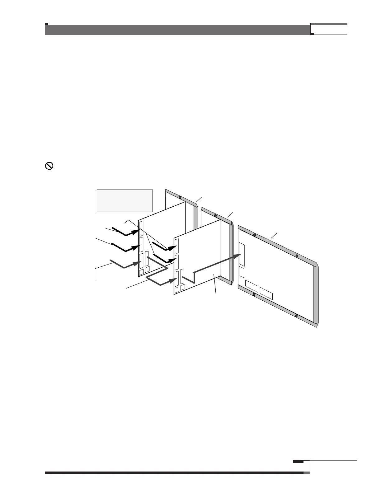
4. Interconnect the MVP Control Module and Dual Chain Module Data Cables
Each Dual Chain Module and Watt Meter comes with a multi-conductor, ribbon-type Data Cable
attached near the bottom, (above the four-conductor power connectors) with an adjacent parallel male
connector. As illustrated below, attach the Data Cable from the Chain Module next to the MVP Control
Module to the connector on the back of the MVP Control Module. Connect each successive Chain
Module’s Data Cable to the male Data Connector on the preceding Module. (Refer to pages 22-30 for
labeled drawings of the rear side of the MVP Control Module, the Watt Meter, and the Dual Chain
Module.)
If your System includes Feature Modules (Watt Meters, Speaker Equalizers, Sound Pressure Meter)
interconnect them now according to the directions that follow.
Do not make Control Cable connections or disconnections with the MVP Control Panel
power cord plugged into an electrical outlet.
Figure 36 – Rear View of the MVP with Data and Control Connections.
Control Module
#1 Dual Chain Module
#2 Dual Chain Module
Multi-Conductor Data Cable
from first Dual Chain
Module to Control Module.
Multi-Conductor Data
Cables from Dual Chain
Module to Dual Chain
Module.
Multi-Conductor Control
Cables from
Switching Module
Chains.
Note: arrows indicate
cable connections,
not signal flow