Matrix System
®
77
Use 10 gauge wire for the connections from Power Supply to terminal blocks. 18 gauge wire may be used
for the Ground, Memory, and 12V Switched path for Head Units, Processors, Speakers, etc. For connecting
power to Amplifiers, use 10 gauge wire for positive and ground instead of 18.
If you have a choice for Power Supply placement, mount it closer to the Amplifiers, since they draw the
most power. Try to keep low-level wiring away from Power Supplies as there may be bleed through. Some
Power Supplies weigh 50 pounds, so usually they are mounted near the floor of the display. (Do not place a
Power Supply directly on the floor, since a water spill or moisture buildup could result in damage to the
System.) Be sure Power Supplies are located in an area with adequate ventilation, since they generate heat.
2.b Paralleling Two Power Supplies
When a car audio display requires more power than one power supply can produce (see
Appendix C) multiple power supplies must be connected in parallel to provide the extra current
reserve (similar to two batteries in parallel – same voltage, twice the current).
NOTE: When paralleling two supplies always use the same size units, e.g. two 35 ampere, or two 50
ampere supplies.
Step 1
Each power supply must have its output voltage adjusted to +13.8 V DC. Remove the
top of each power supply and locate the circuit board. There is a thumb-wheel adjustment
on the underside of the circuit board. With the Power Supply plugged in and turned on, use
a voltmeter connected to the output terminals to adjust the output to +13.8V DC (as close as
possible, plus or minus .2V). Replace the top cover.
CAUTION: there is 110V current under the cover – be careful to avoid shock.
Step 2
Mount the power supplies in the display and connect to the rest of the System as shown in
figure 41.
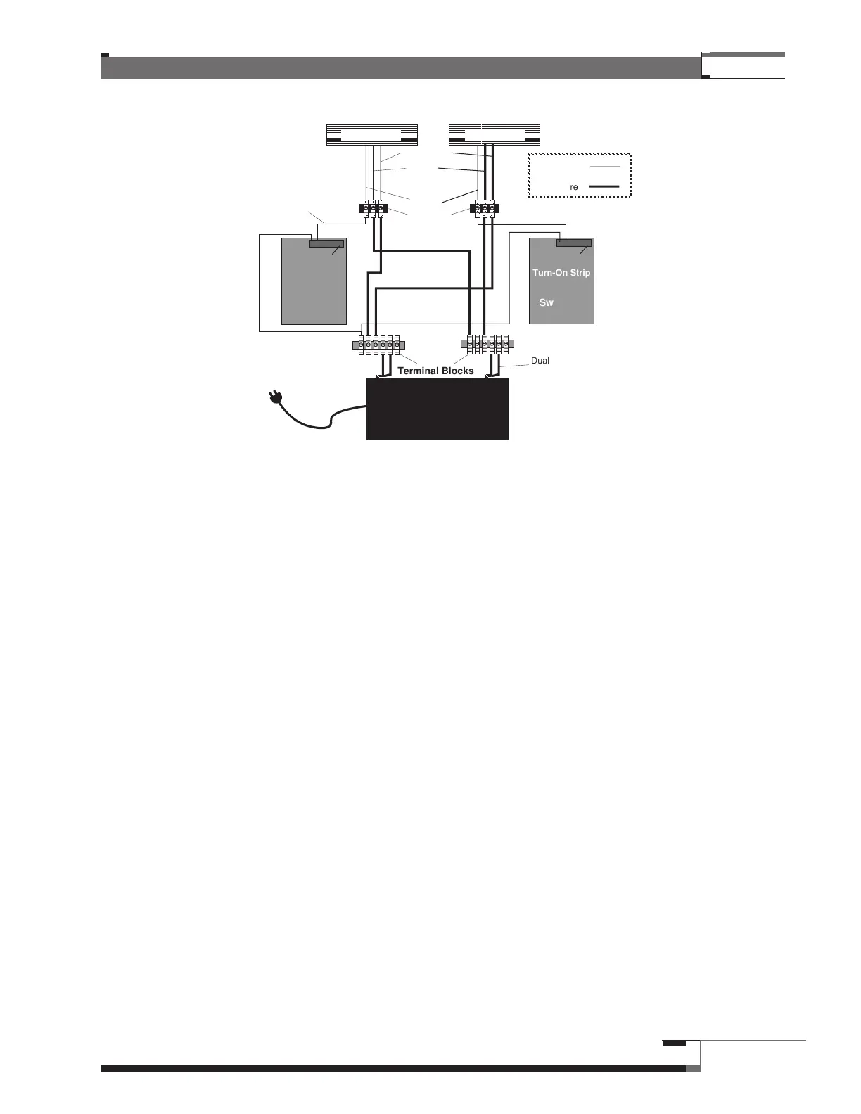
Figure 41 – Component Power Supply Installation for Switched 12V
Terminal Blocks
Dual 10 ga. wires
Switching
Module
+12v DC Switched
Deck Amplifier
Component
Turn-On Strip
Switched
12v+
12v Memory
Ground
+
-
Terminal
Blocks/PDQs/
Push Terminals
Positive
Negative
Power Supply
18 ga. wire
10 ga. wire
Switching
Module
Component
Turn-On Strip