Matrix System
®
67
MVP Control Panel Installation
Because of the variety of configurations that are possible with Matrix System MVP Control Panels, there
are many “right” ways to install the various Modules in your MVP Control Panel. Following are
suggestions for layout and a sequence of steps that will help you accomplish the job.
1. Plan the MVP Control Panel Layout
The MVP Control Panel Modules can be positioned anywhere in your display, but the Data Cable
connections between Modules should be run in a certain order. These are the general principles that we
use at MTi, and that we suggest you use to plan the layout of your MVP Control Panel:
1.1 Locate Source Modules adjacent to the MVP Control Module. Position Processor Modules
below or adjacent to Sources. MVP Control Panel Modules are usually positioned from
source to processor to destination, following the normal signal path of audio/video
components; and from left to right, and top to bottom, in the same direction as lines of
type on a page. Most people are more comfortable with this configuration. This
maintains a logical order for the Infra-Red Remote Control.
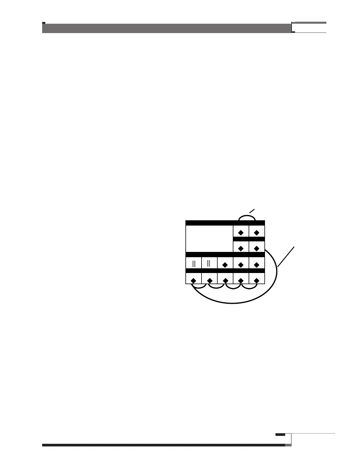
1.2 If your MVP Control Panel has an
over/under layout, you may find
that the data cables attached to
the Chain Modules are not long
enough to run from the top right
Module to the lower left. MTi
makes a special Data Extension
Cable for this purpose. If you
did not specify this in your order,
please call Customer Service
and we will be glad to send
you one.
1.3 Locate Amplifier Chains in the
same Dual Chain Module above
their respective Speakers (i.e.,
Front Amps above Front
Speakers) if you are not using
Watt Meters.
1.4 If the System includes Watt
Meters they can be used with either
the Amplifier or Speaker Chain. If they are used with an Amplifier Chain, special wiring
and switching can be employed so that the Watt Meter is activated only when its
Amplifiers are included in a demonstration system. Call MTi Customer Service for more
information.
1.5 Position each Speaker Equalizer adjacent to the Speaker Chain it will equalize. For
visibility, if you have a Sound Pressure Meter, you may want to install it on the right-hand
side of your MVP Control Panel.
Control
Module
Attached Data cabl
Data Extension
Cable – connects
DCM #2 to DCM #3
1
2
3
456 7
DECKS PEQS
EQ AMPS
WATTS FRT AM
SUB AMP
SUB SPKR. SPKFRT SP
TWT
XOVRS
WATTS
R. AM
Figure 35 – Over/Under Control
Panel Layout